|
Written By Walter Lavogiez |
|
As with the other "How To" articles on this site the informatio presented here is for informational purposes only, and neither the author nor the site owner accept any responsibility for errors, ommissions, or inaccuracies. This information is thought to be correct for the 2000 Dodge Durango but anyone using it should be cautious if something looks different on their particular vehicle, and determine what the difference might be. Also notice that the sound system in this article is the premium Infinity sound system and not the standard system. The "Standard" system consists of four standard speakers and a AM/FM cassette tape radio. It does not have the external amplifier mentioned in this article. (Thanks for pointing it out, John) All photographs in this article are links to larger images. Click the image to view the large photograph. The time has come to change the car radio of my 2000 Dodge Durango. For several reasons, the most important being that I want the new car radio to be able to read mp3 format, from an USB device, and also from an I-Pod. The 2000 Dodge Durango is equipped with a stock Chrysler sound system, composed of:
The problem is that the stock radio is in a 1½ DIN format. This format means 3 inches (7.5 cm) height. Most of the aftermarket car sound systems are either in 1 DIN format (2 inches / 5 cm height) or 2 Din format (4 inches /10 cm height). * Note: actually, to be accurate, 1 inch = 2.54 centimeters I have considered for a while the opportunity to purchase a 2 DIN sound system, with LCD graphic panel, in order to have also a GPS, but I quickly forgot this possibility, according to the complexity of the transformation to be made in the dashboard. I decided to install a standard 1 DIN Alpine CDE-104BTi Car Stereo, without GPS. The following write-up is intended to:
I will not, for now, explain how I installed the new Alpine sound system. Just to say: -As I am located in Europe, I had not any easy way to find electrical adapters to fit between the stock (Chrysler) connectors and the new Alpine radio connectors. In this context, I did not want to order a kit without the possibility to try it before. -I decided not to re-use the Chrysler amplifier, as I had enough audio power (4 x 50W RMS) from the Alpine new system. I know that a special Chrysler kit exists, allowing to bypass the Chrysler Power Amplifier without to remove it. As I dont have such a kit, I just removed the Amplifier and made "home wiring connections" to bypass the Amplifier. Thus, I did a number of "cut and rewire" within the stock electrical connections. This process is only one-way. After having cut electrical wires, returning to the stock connections will remain another "cut and rewire" process, letting a lot of dirty connections in the electrical wiring. So, prior to go for this kind of installation, ask car radio and/or car electrical professionals, as adaptation kits might well exist for this operation. I also replaced all the 6 speakers by a JBL kit : 2 bass/medium and 2 tweeters in the front doors, JBL GTO6508C 2 two ways speakers in the rear doors: JBL GTOxxxxx Also, this article does not explain how to change the speakers, as the subject has been covered by Scott Craig in an above article.
Description of the stock Chrysler Stereo connections
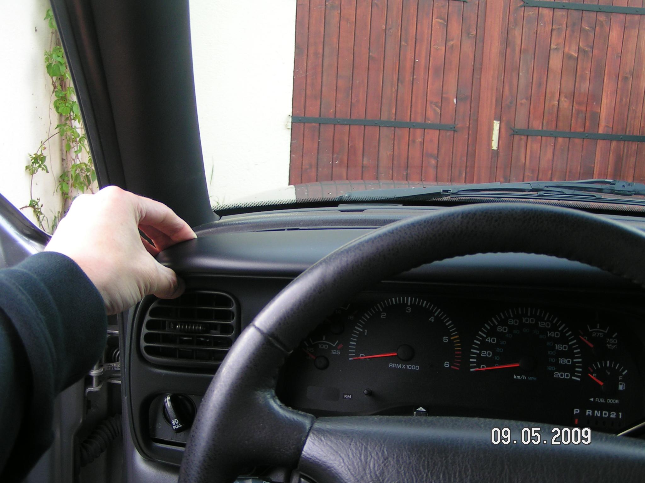
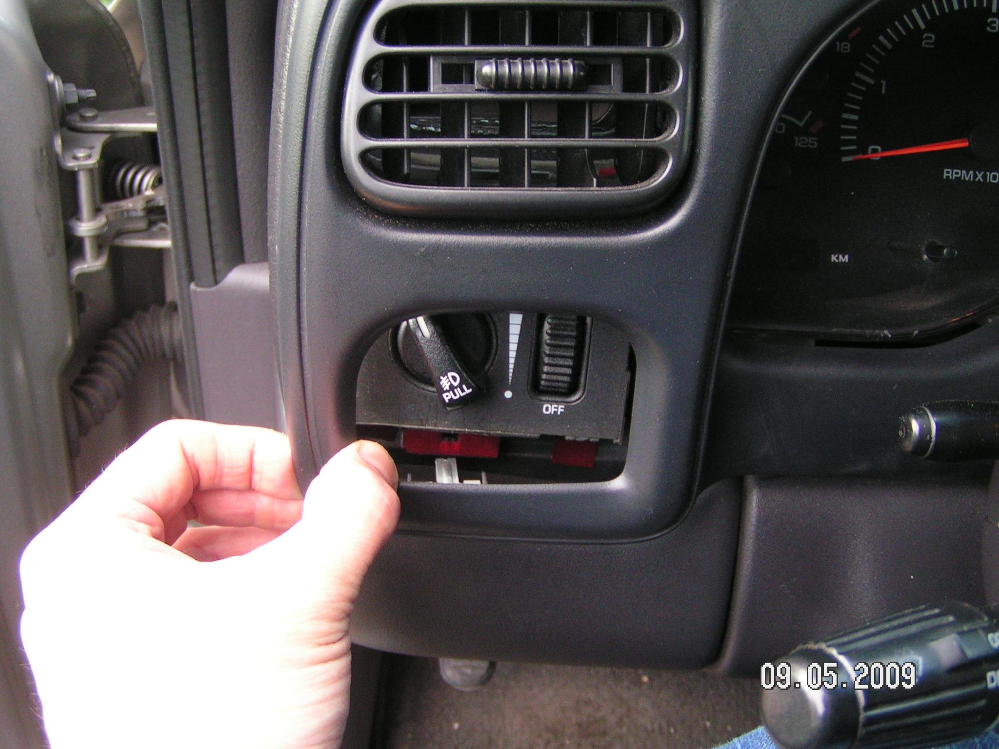
How to remove the stock Chrysler car Stereo This operation is very easy, thanks to Scott Craig for his hints in the following operation. Attention: For your security: although I did not do it, prior to make any operation, you should: This is for disengage the air-bags sensors. First, remove the front plate. Gently pull in the upper left corner with your hand as seen in the picture below. There are no screws to remove, all is clipped:
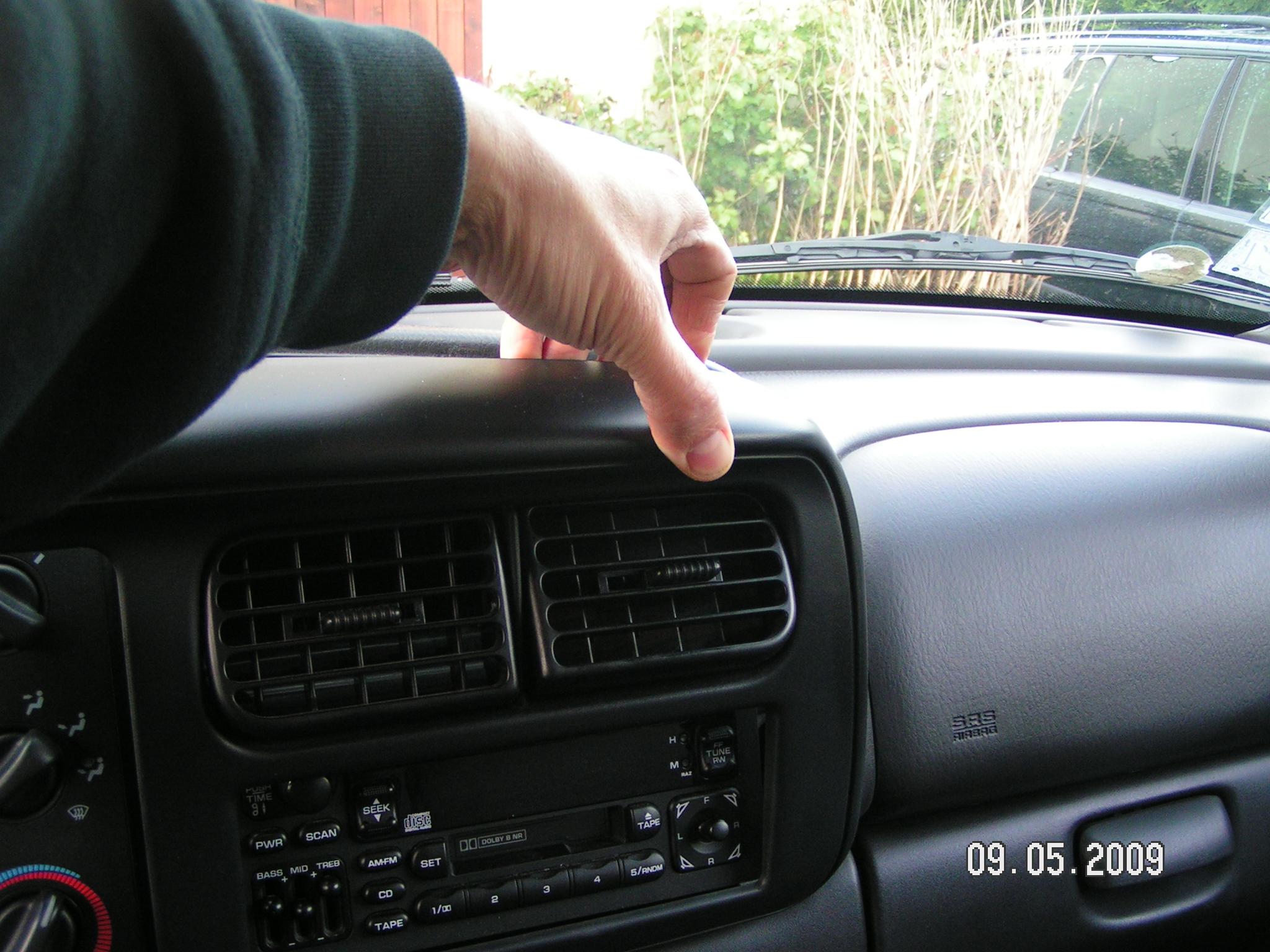
Pull delicately all long the upper side of the front plate:
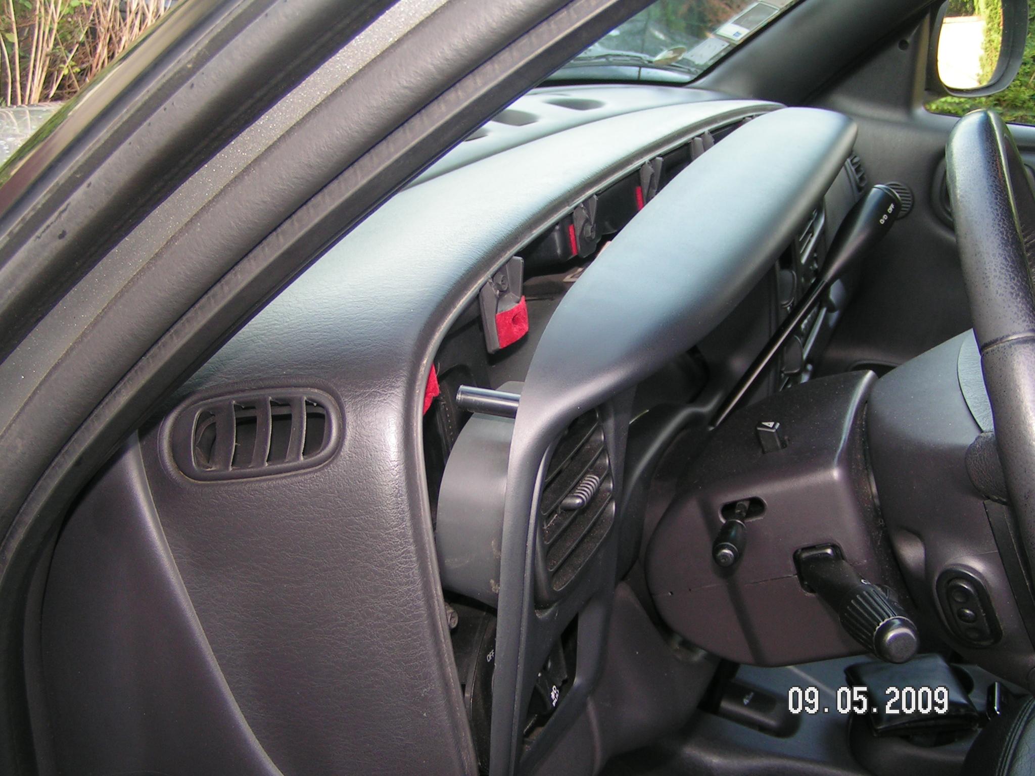
Then pull again from the lower right corner of the plate:
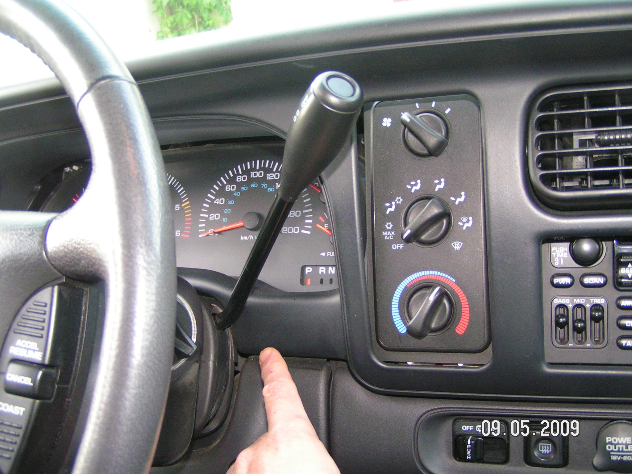
You cannot pull beyond this point. You now have to move the gear selector in the lower position:
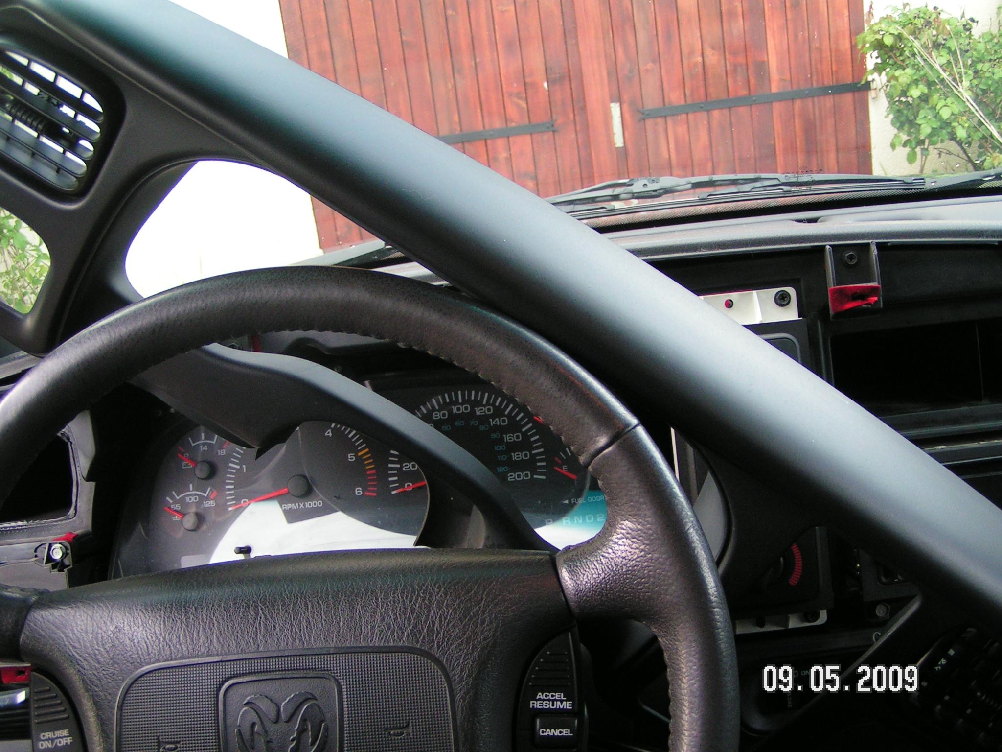
Ok I know, you will have to put the ignition key on (do not start the engine), and deal with this boring beep-beep for a few seconds J When this is done, slide the front plate clockwise as seen below:
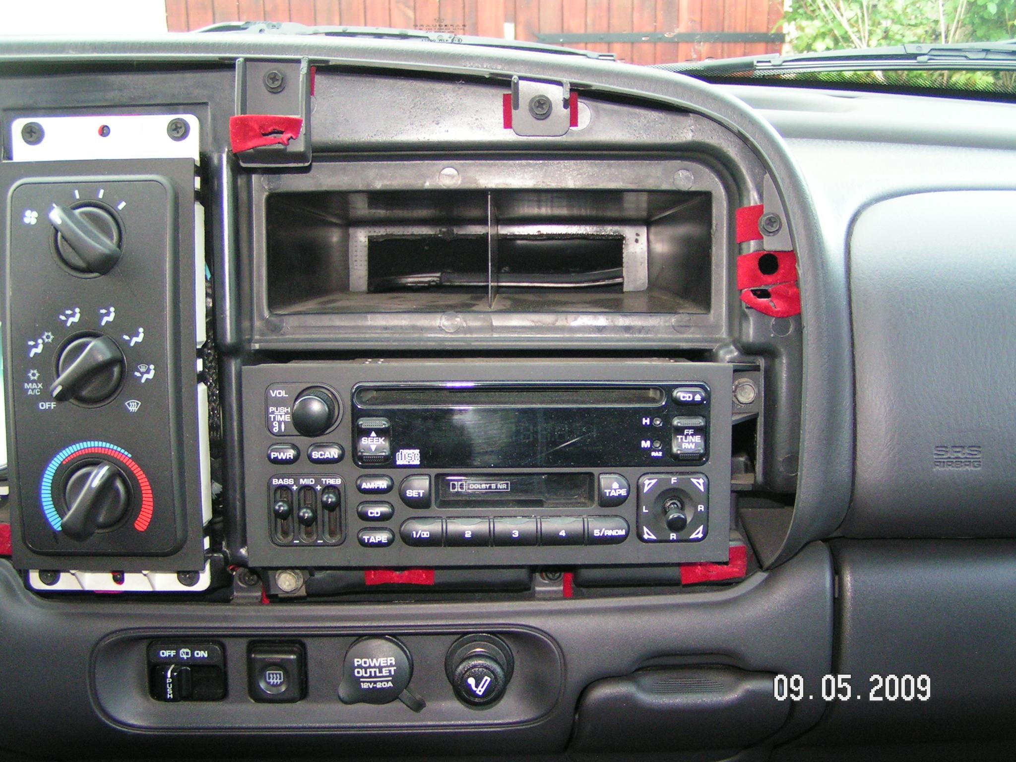
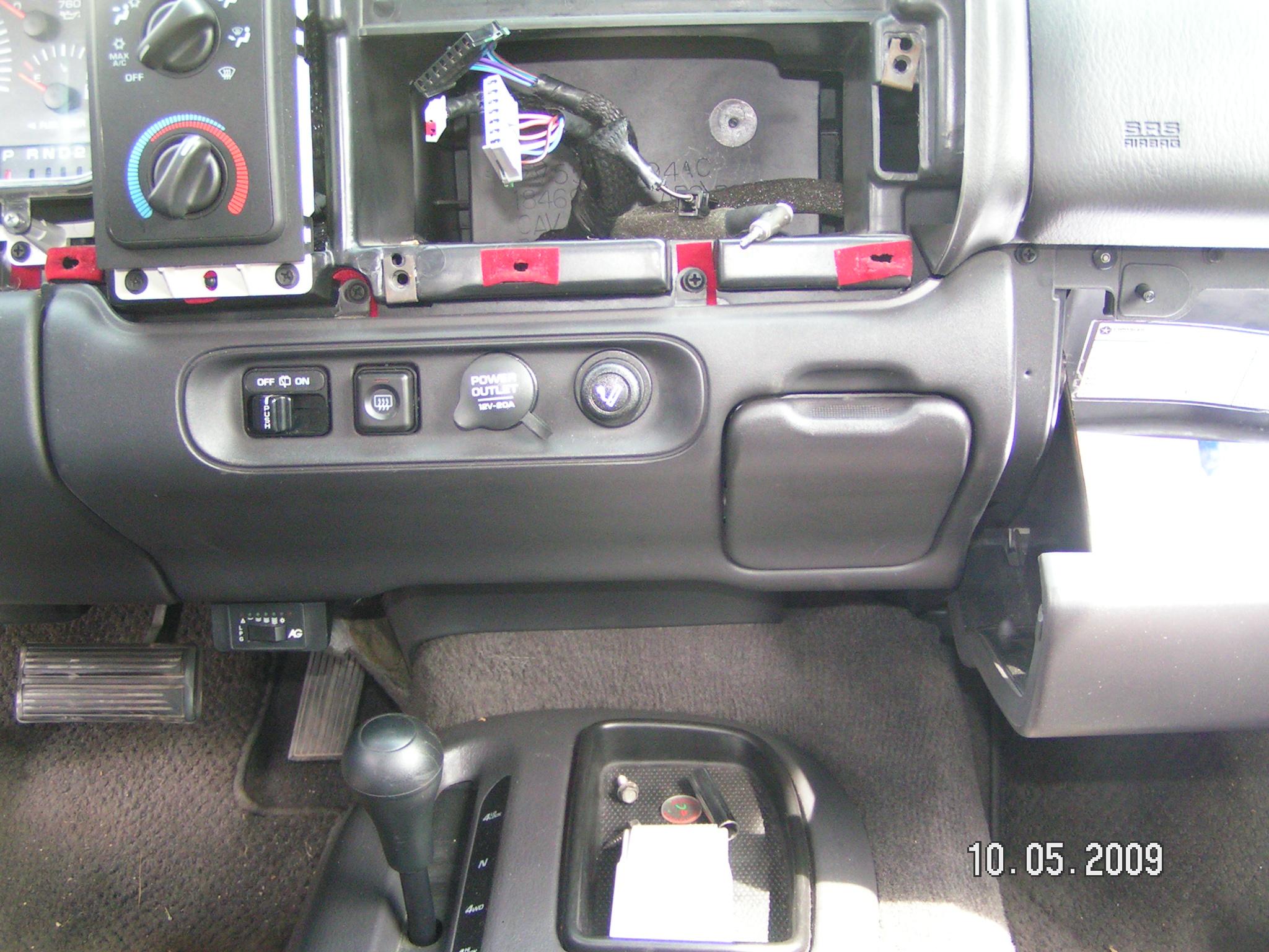
You should now be able to remove entirely the front plate. Put the gear selector back in its upper position and put the ignition off. Now you can see the stereo, attached with its two bolts:
Remove the two bolts and the radio will slide out easily. There are two connectors with the wiring diagram printed on the upper side of the radio unit. Both gather the 8 sound wires (2 wires per channel) plus the service inputs, +12V battery, +12V ignition, +12V dimmer, ground. There is also a little connector with two wires, which I have no idea of its use, and finally the antenna connector. Update - I have been told that the 2-pin connector is for the volume control on the steering wheel. Thanks Joseph
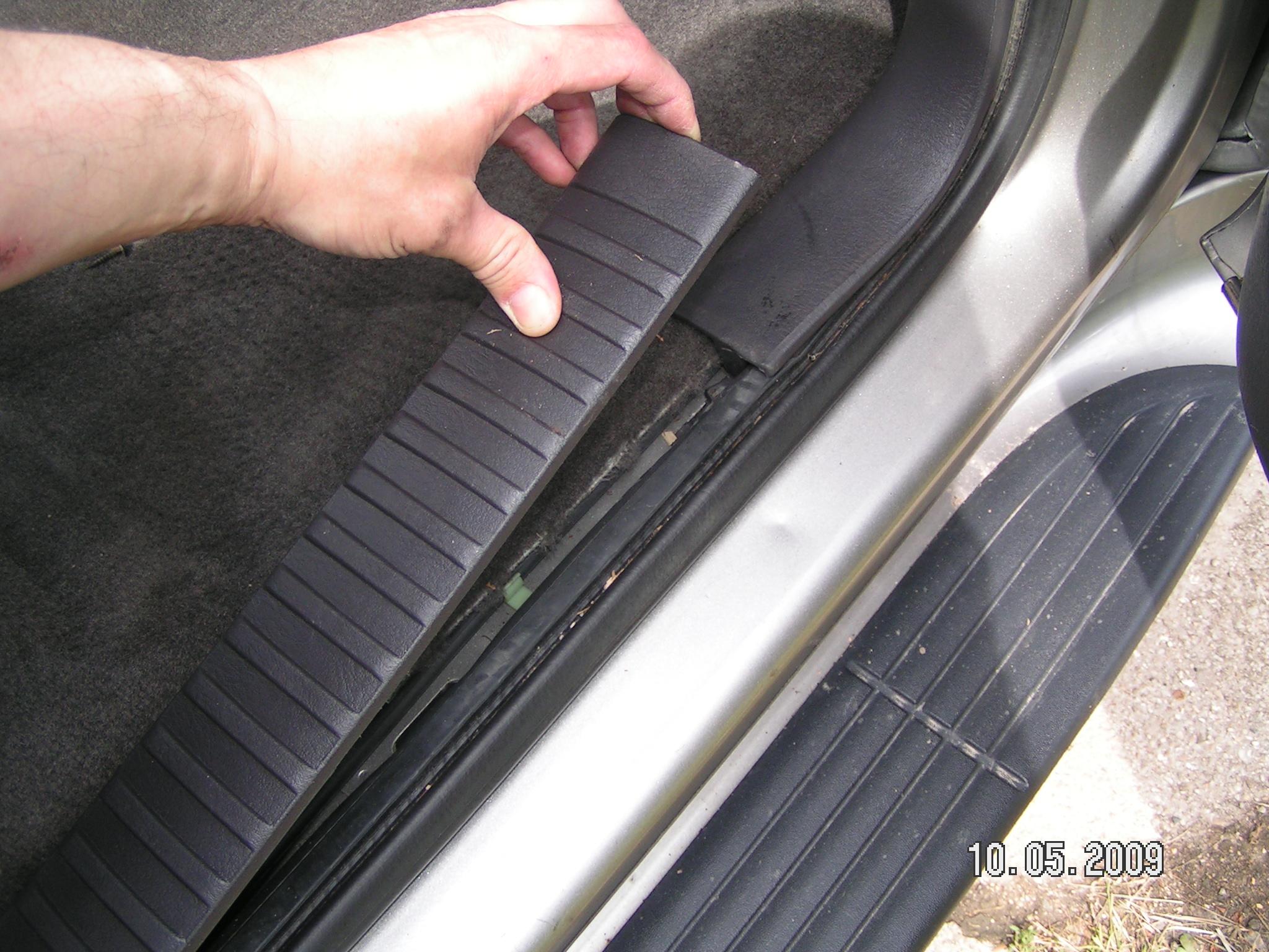
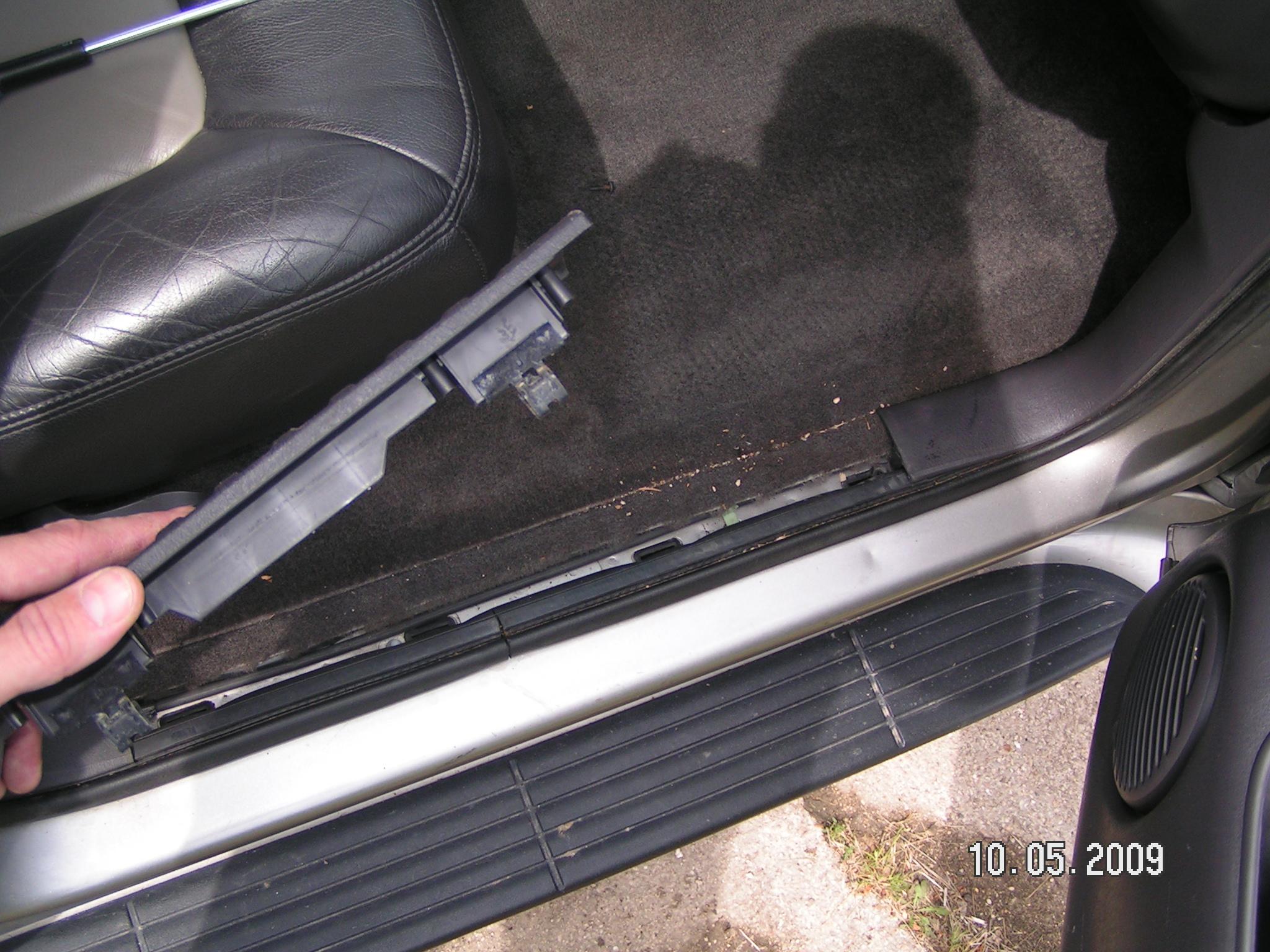
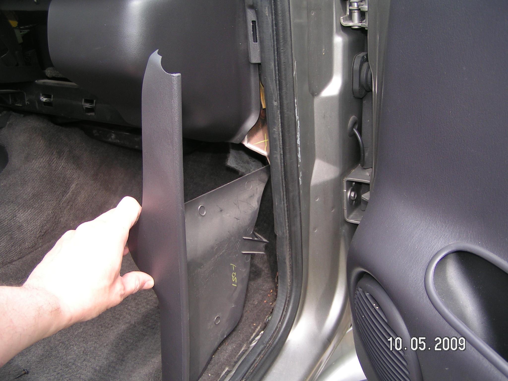
How to remove the Power Amplifier The power amplifier is located along the bottom right side of the front passenger. First remove by hand (no screws) the right "walk panel" as seen in the pictures below:
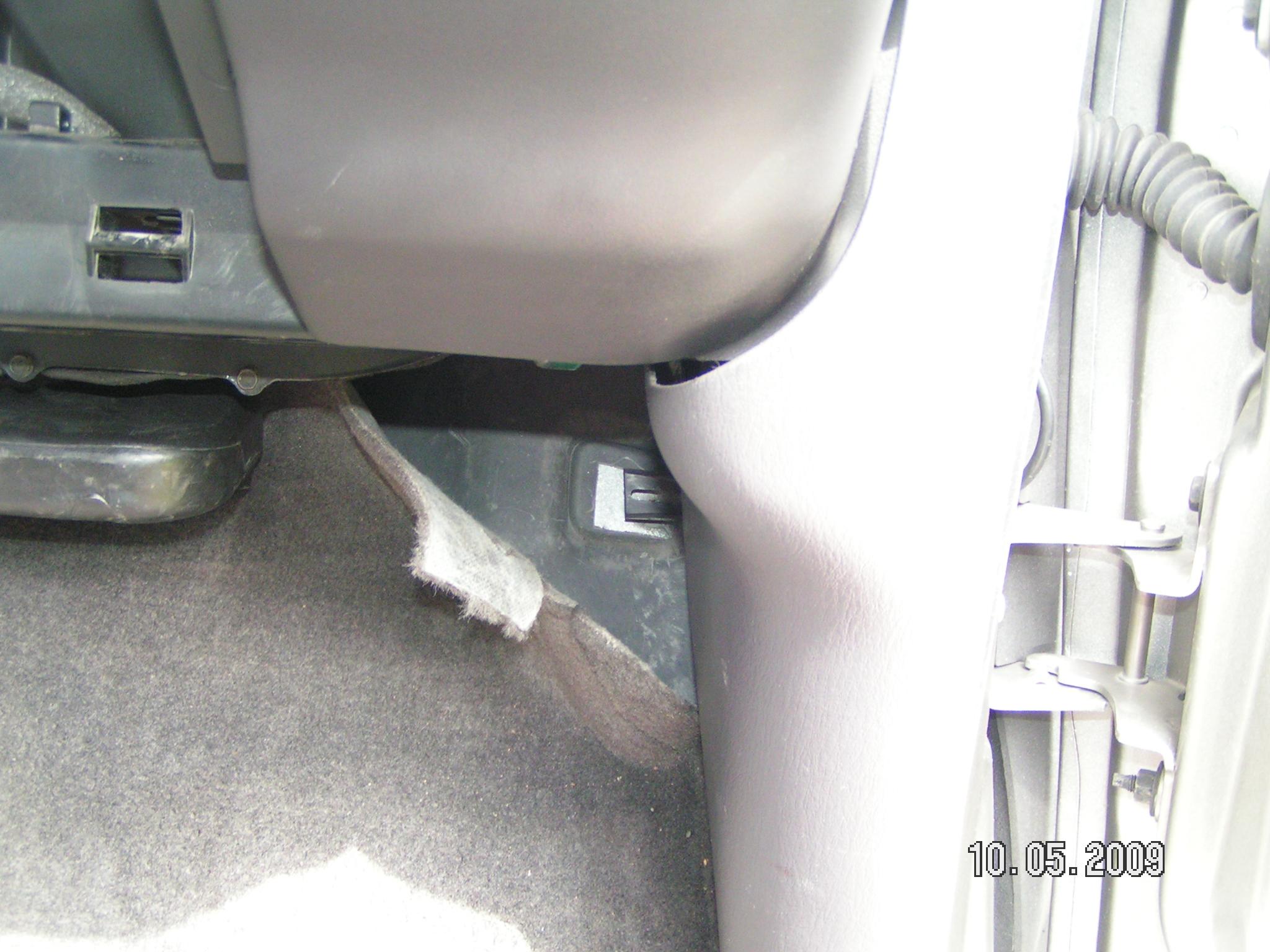
Gently pull off a portion of the ground carpet, there will be a screw on the upper right corner on the floor, remove it:
*Note on the above picture: I had removed the glove box, which was actually not necessary to do. Then pull backward the right panel:
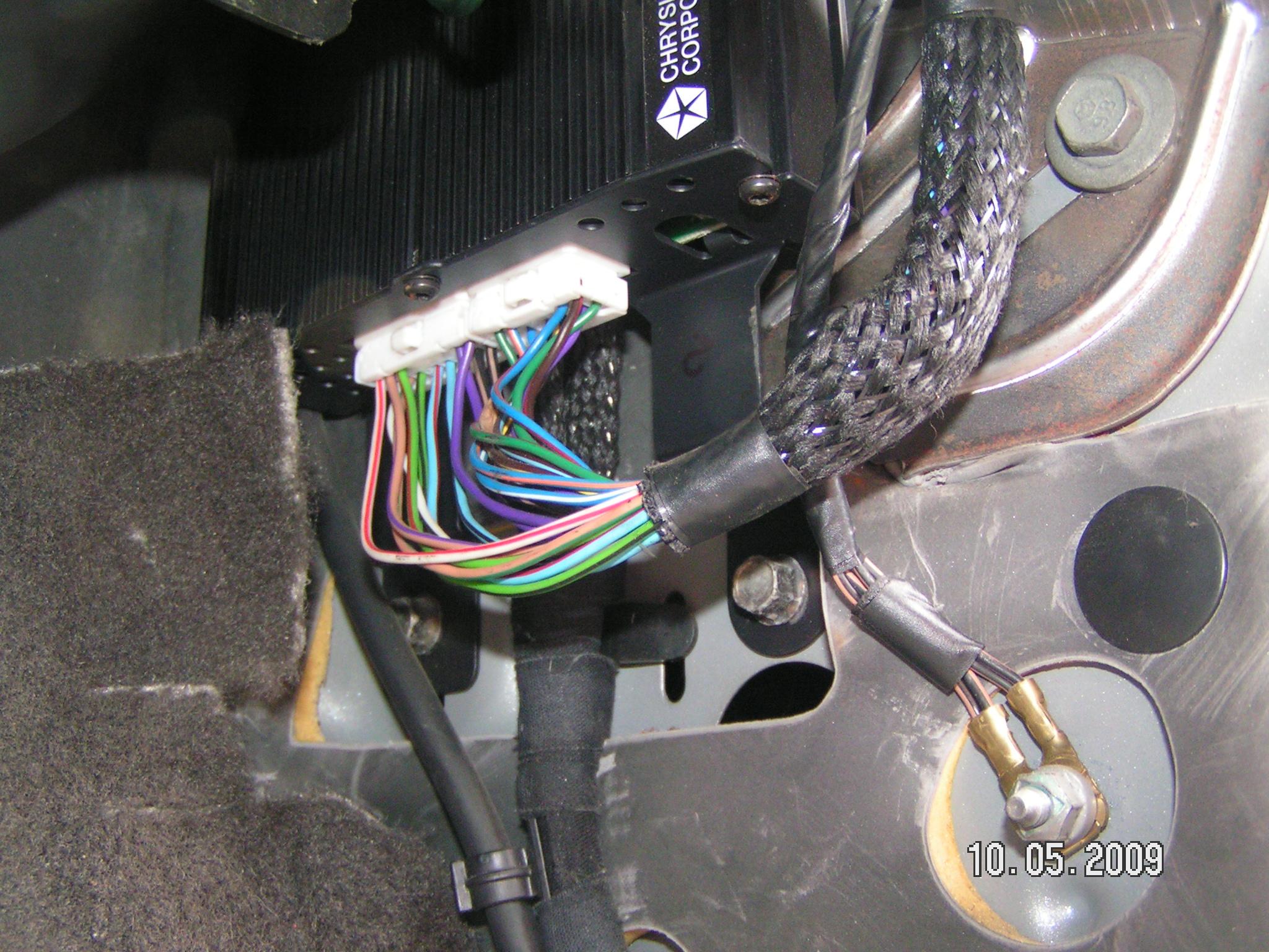
Now you can see the power amplifier:
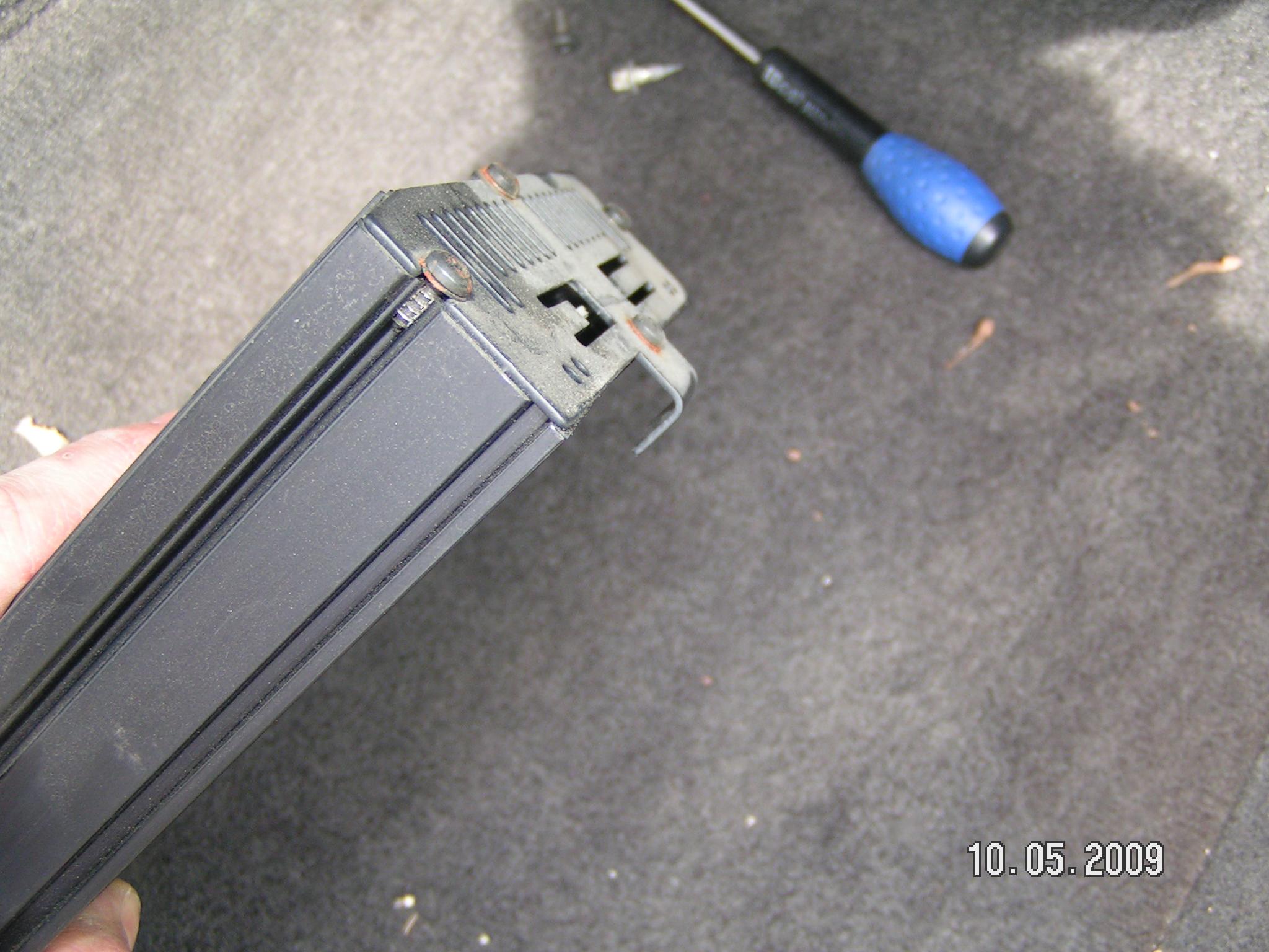
The amplifier is attached with only the two bolts you can see on its down side on the picture above. The upper side is simply hooked, to understand this, please consider the picture below:
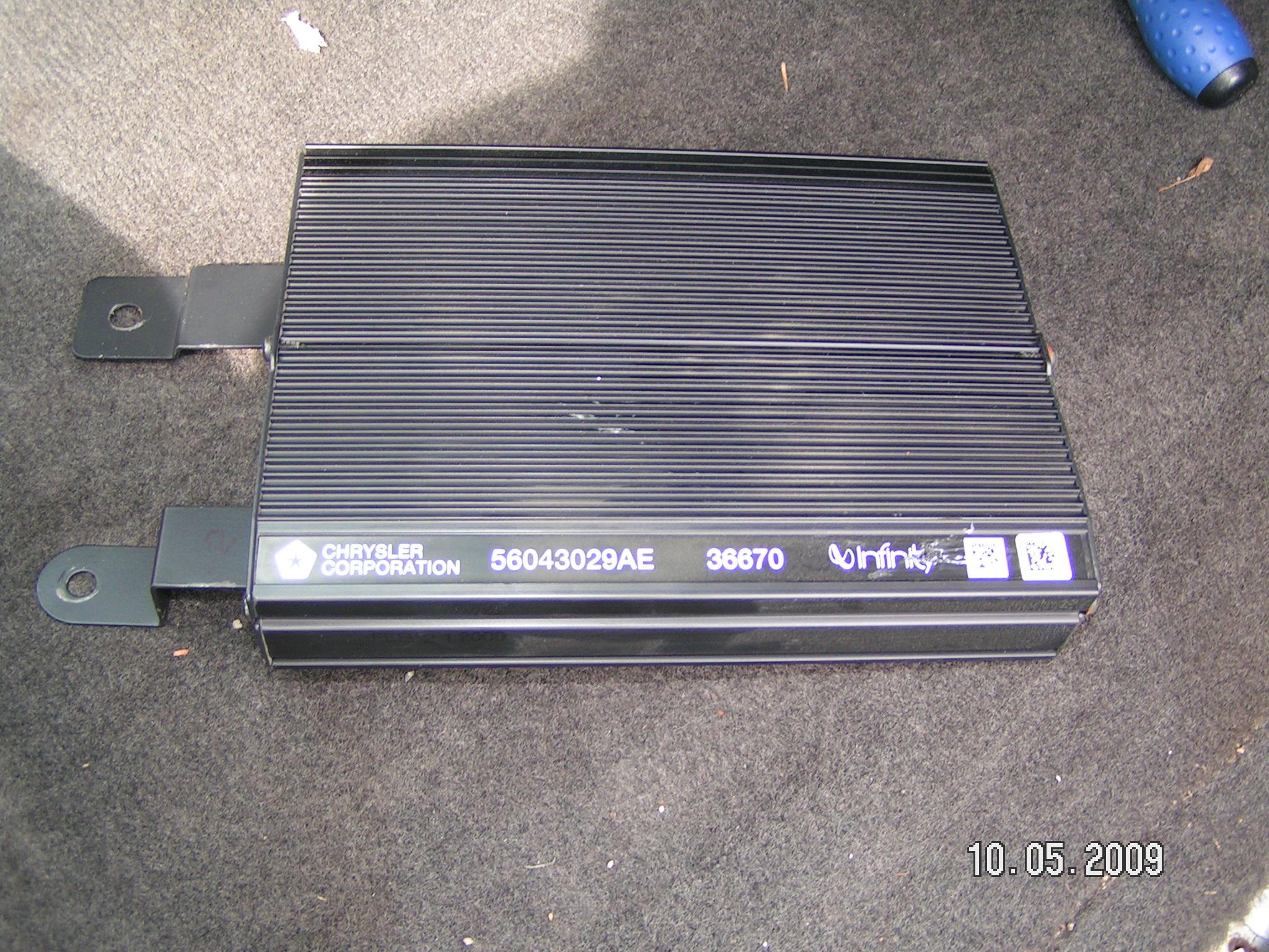
Thus, to remove the amplifier, remove the two connectors, remove the two bolts, push the amplifier upward, and then try to pull it away from its upper hook arrestor. I must confess that this has been the hardest part Just be patient and try again and again, I did not find the easy way to do it. This is a picture of the amplifier when removed:
To put back all this stuff, just follow all the above operations in the reverse order. |