Built by Scott Craig -- October, 2004 through July, 2005
|
|
|
CONSTRUCTION PHOTOGRAPHS AND NOTES Built by Scott Craig -- October, 2004 through July, 2005 |
| CONSTRUCTION PHOTOGRAPHS - 11/07/04 |
 |
 |
 |
 |
 |
 |
|
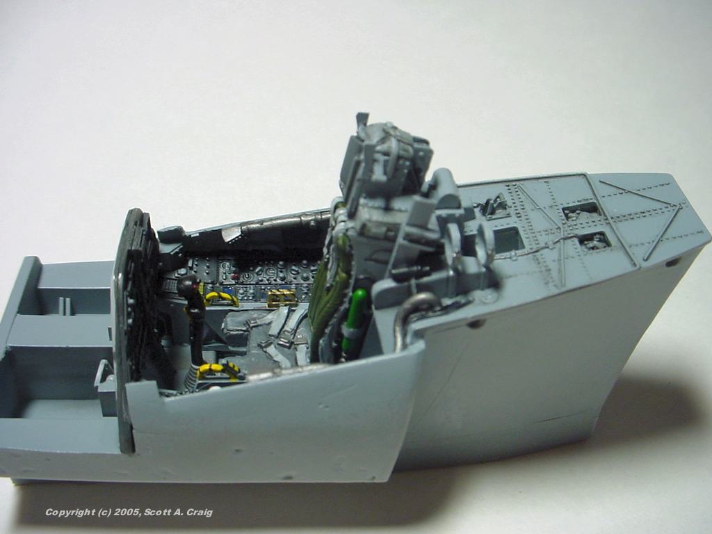
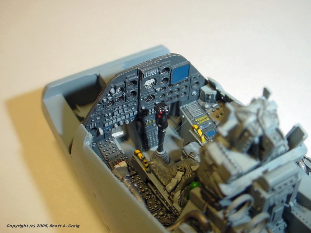
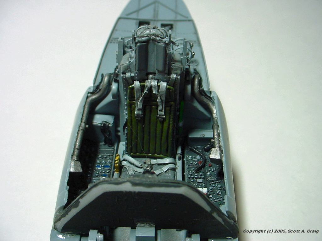
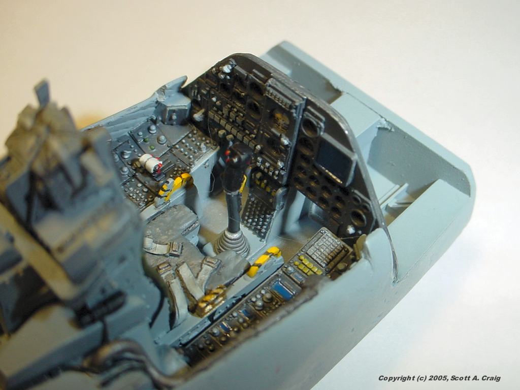
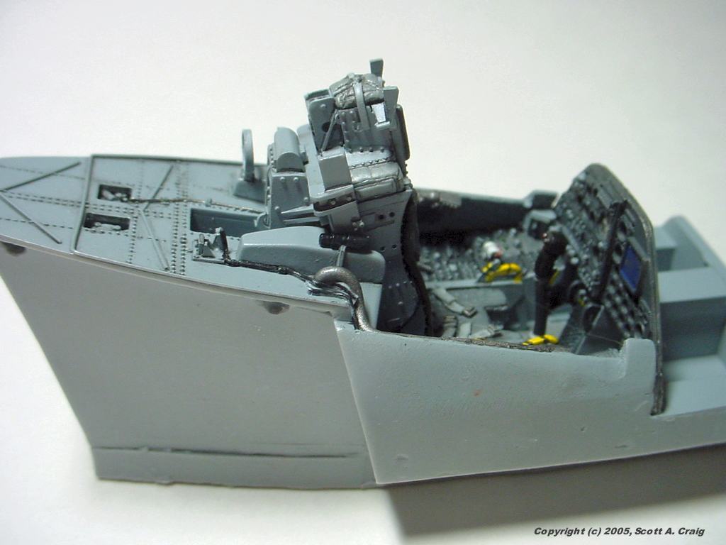
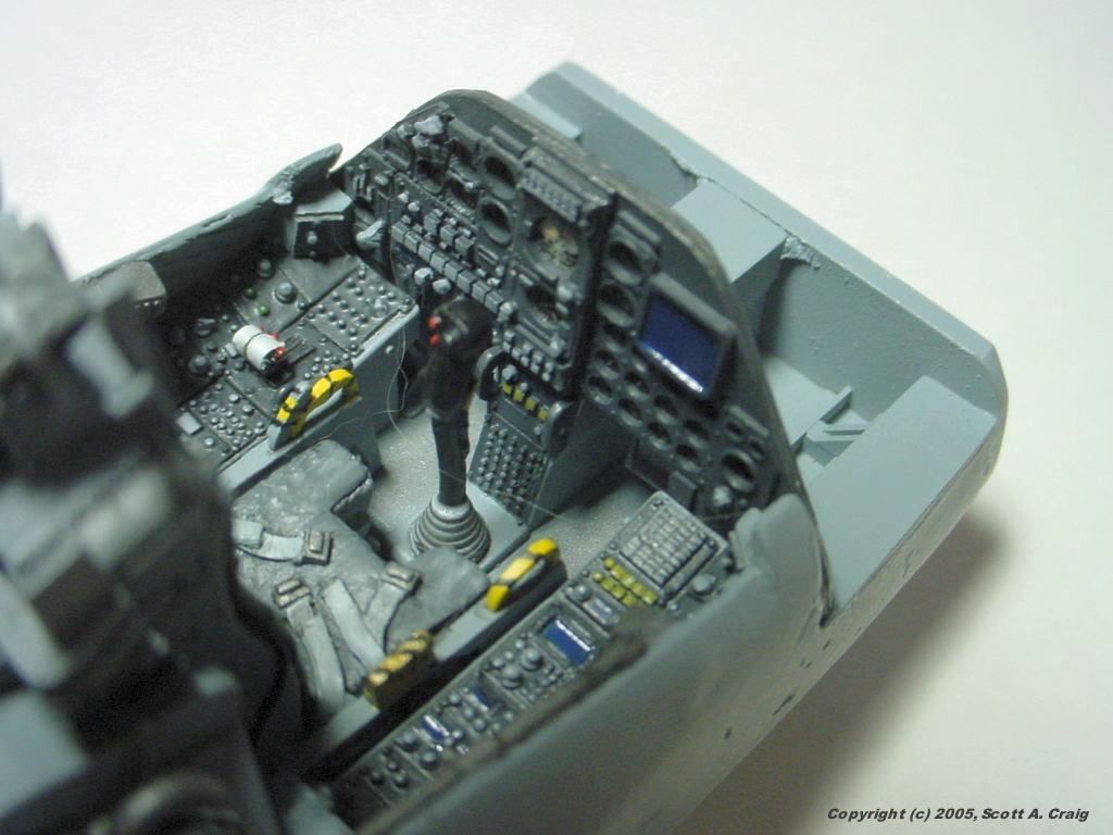
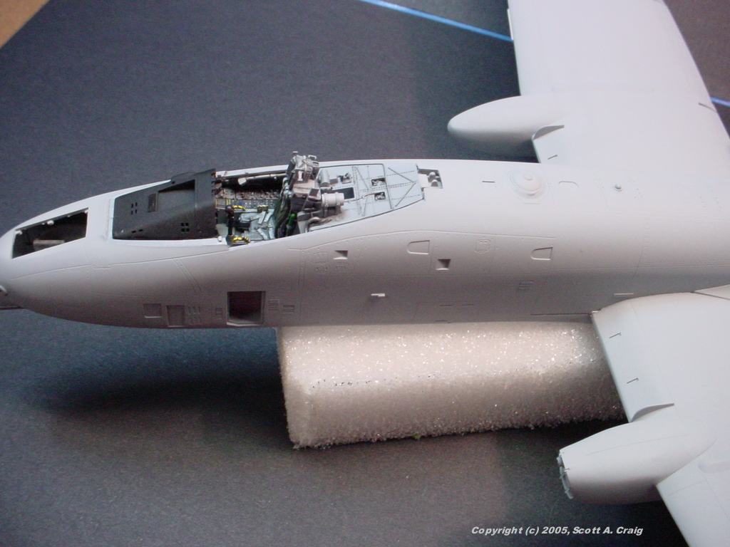
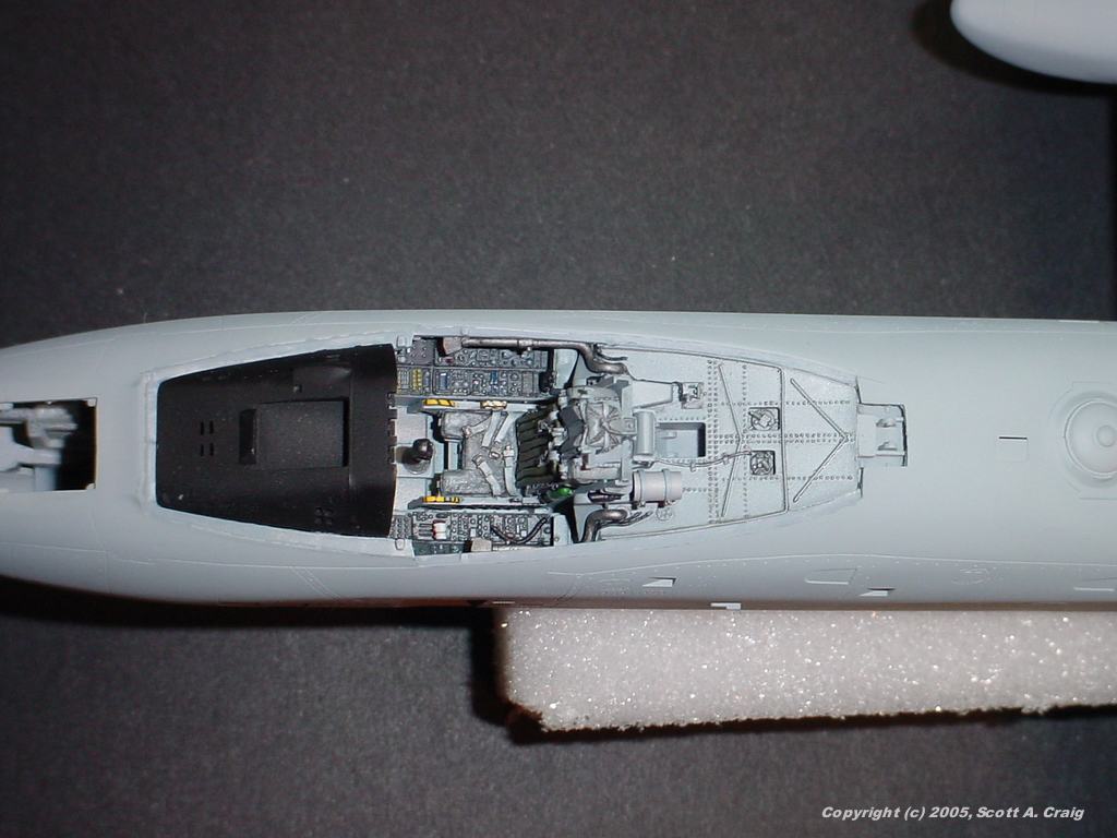
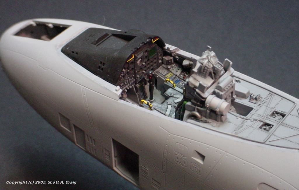
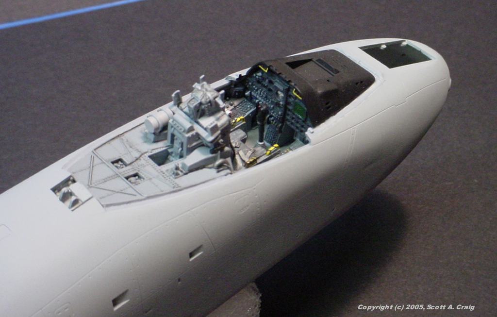
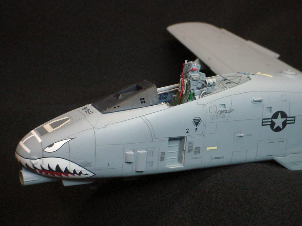
This is the main section of the Cutting Edge cockpit conversion The detail is excellent, however as noted in the Construction Notes below, it does have a couple of problems. The casting in general is smoother than some other resin cockpits I've used, and the parts are much stronger. Since these pictures were taken I changed the color of the Maverick screen on the main display from blue to dark green. I originally painted it blue based on a picture I had, but after looking at a couple of others I decided that the blue was caused by a reflection of the sky above when the photo was taken. It was an easy fix :) Also, I did get the cat hair out that shows up in the larger photos :) | ||
 |
 |
 |
|
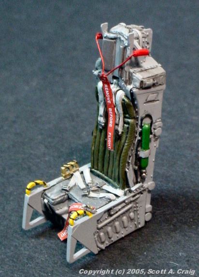
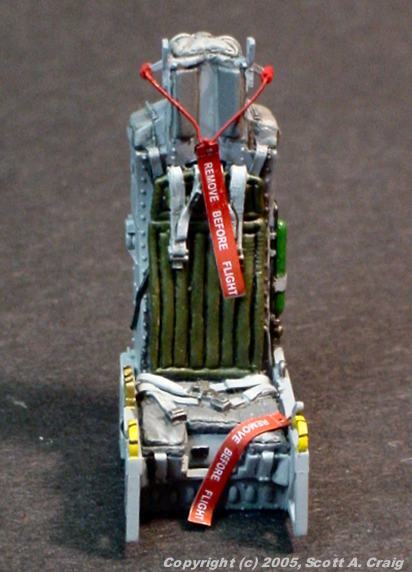
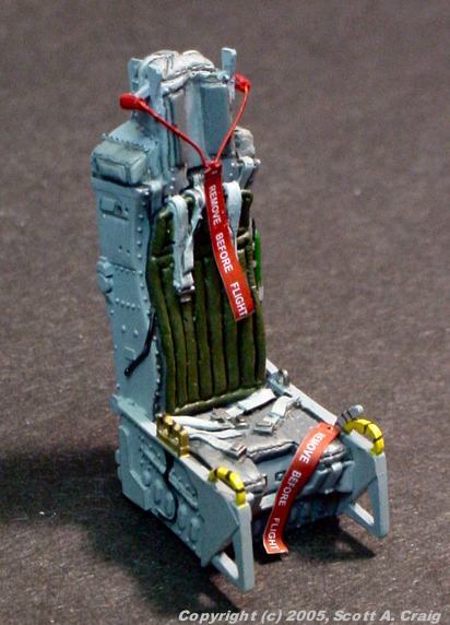
These are photos of the ACES II seat that comes with the Cutting Edge conversion. Even though I had the seats done at the same time as the cockpit, except for the Remove Before Flight flags, the photos were taken on May 3, 2005. The Remove Before Flight streamers are Eduard photo etch parts. They look a bit big for the seat, but believe it or not these are 1/48 streamers on a 1/32 scale seat. You should see the 1/32 scale flags! The RBF flag that drapes in front of the seat is actually wrong. It should go diagonally across the seat. On the left side of the seat (the right side in the photos) it pins the seat release safety and on right side it pins the manual parachute release (the gold and black shape on the edge of the seat in photo 7). I found out about the manual 'chute release safety after I had installed the flag and I'm not sure I can get it off without making a mess now so I will probably just add a third flag. I also need to repaint the straps that go from the seat pitot tubes to the flag hanging in front of the seat. I painted them red but they should actually be yellow. One cool thing about the Cutting Edge set is that the seat actually slides down into the rails in the cockpit. You can see the little rollers on the back of the seat in photos 7 & 9, and you can see the rails sticking up beside the seat in photo 3 above. The seats don't have a blue cast to them that photos 8 & 9 seem to indicate, that's just my fluorescent bench light. They are painted Dark Ghost Gray and photo 7 is closer to what they actually look like. | ||
| CONSTRUCTION UPDATE -- 04/15/05 |
 |
 |
 |
 |
 |
 |
 |
 |
 |
|
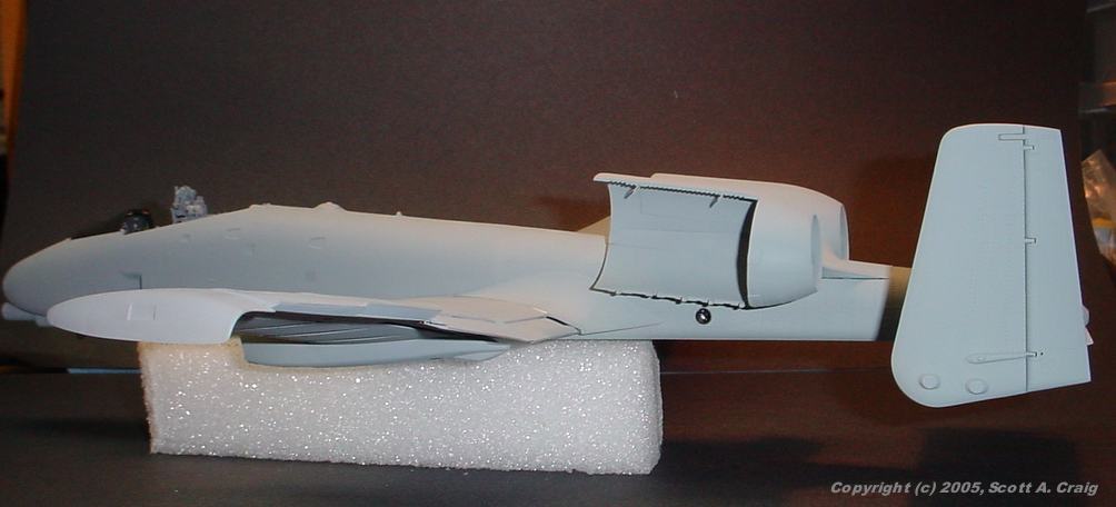
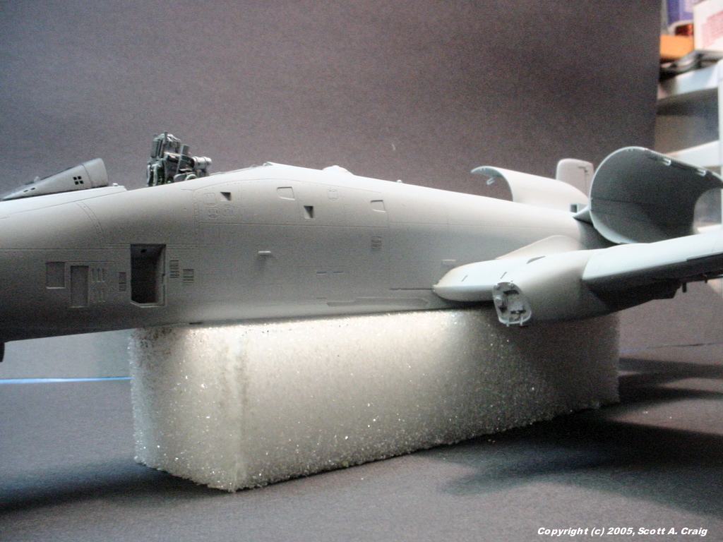
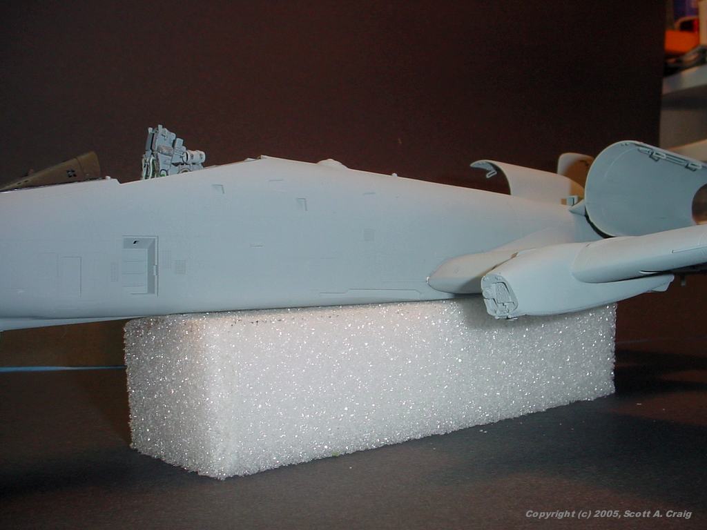
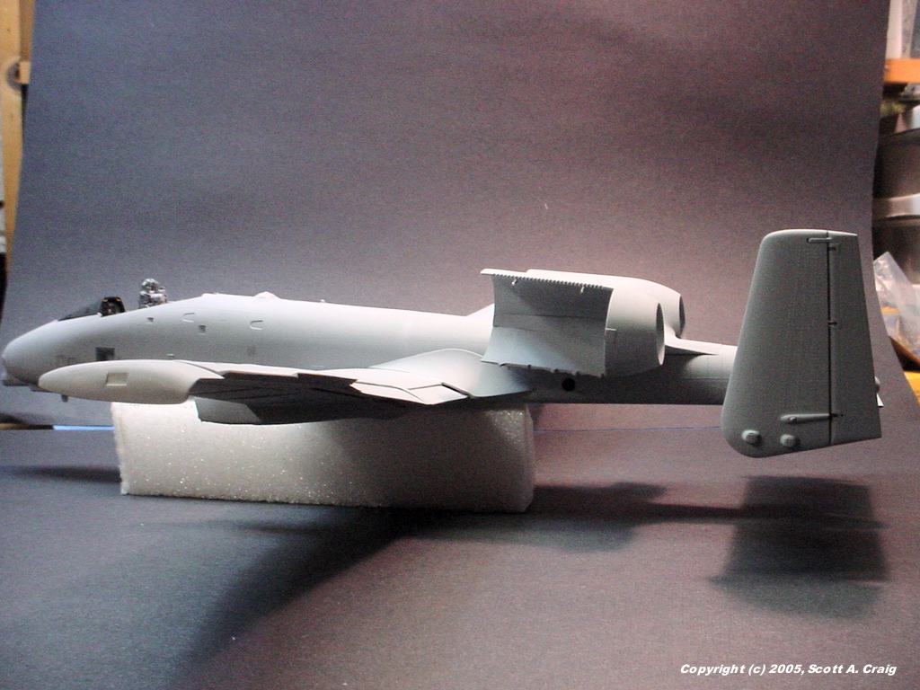
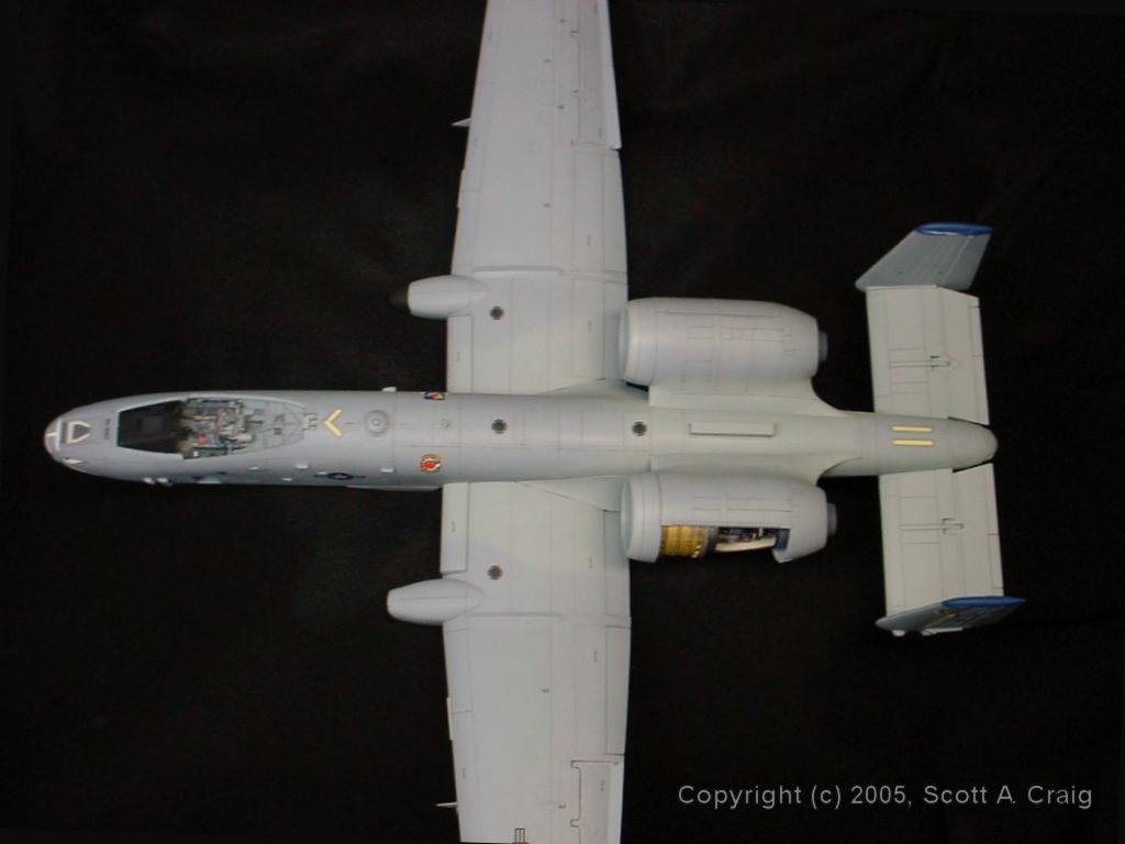
Progress at last! What you see in these photos is 105 hours of construction time already. I am so tired of sanding and filling and priming and sanding and filling and priming ..... In places I've gone through that routine 4 or 5 times. When I thought I had it right I'd find out the hard way that I didn't. I've used styrene rod, styrene sheet, putty, gap-filling cyanoacrylate, white glue, and everything else I could think of to fill the gaps, but I think I finally got all the visible seams out except on the left wing. There are still a couple of shims between the left wing and fuselage that I haven't sanded yet. Hopefully all the other gaps are supposed to be there (this *IS* a Warthog, and it isn't a smooth-body!) or there are other parts that will cover them. The engine pods are not permanently mounted. If they look strange in the photos, or you see some gaps between them and the fuselage, that's why. I just stuck them on the fuselage for the photographs. | ||
| CONSTRUCTION UPDATE -- 04/16/05 |
 |
 |
 |
 |
 |
All images above are links to larger photographs. Click the image to view the larger image |
|
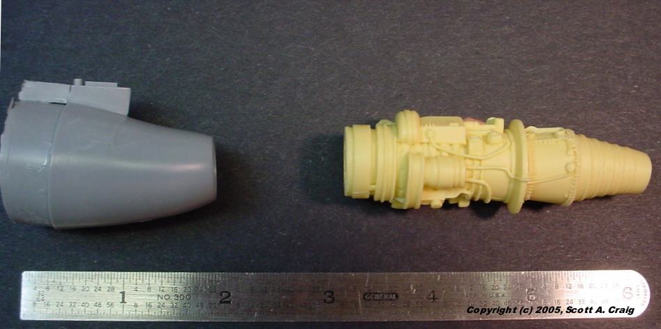
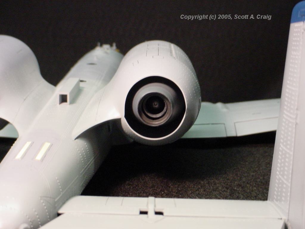
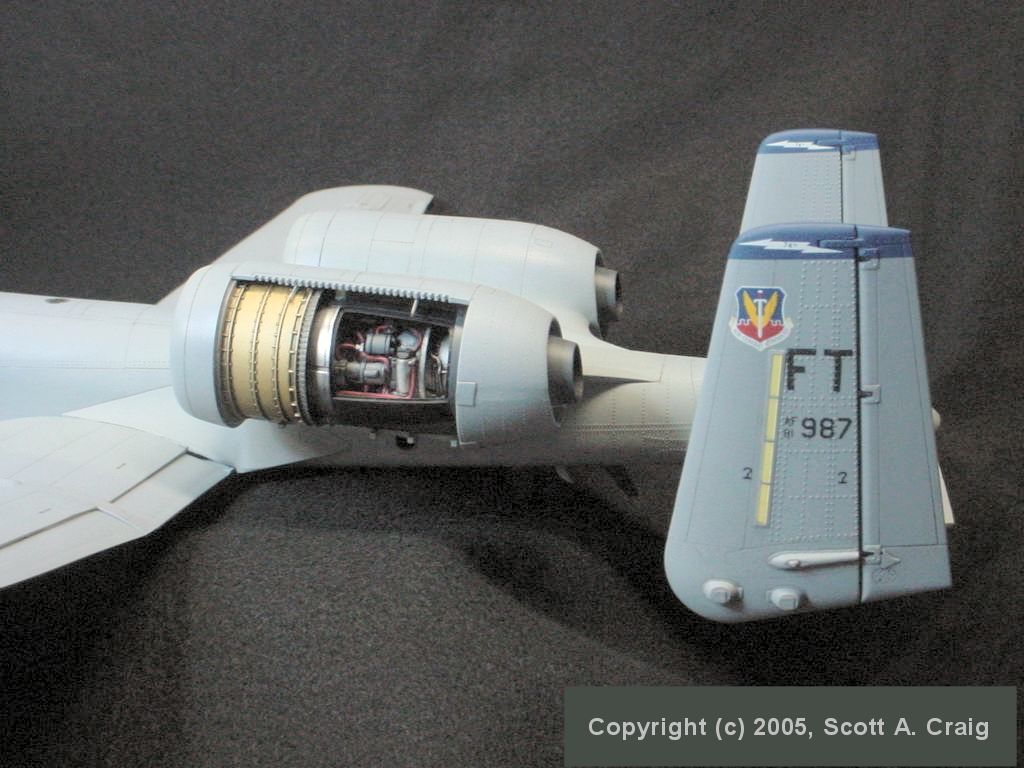
OK, here we go with the engines. They are really nasty, at least mine are. A person
who has the N/AW version tells me that his engines are hollow, but as you can see in the "Miscellaneous
Areas" construction notes below mine are far from being hollow.
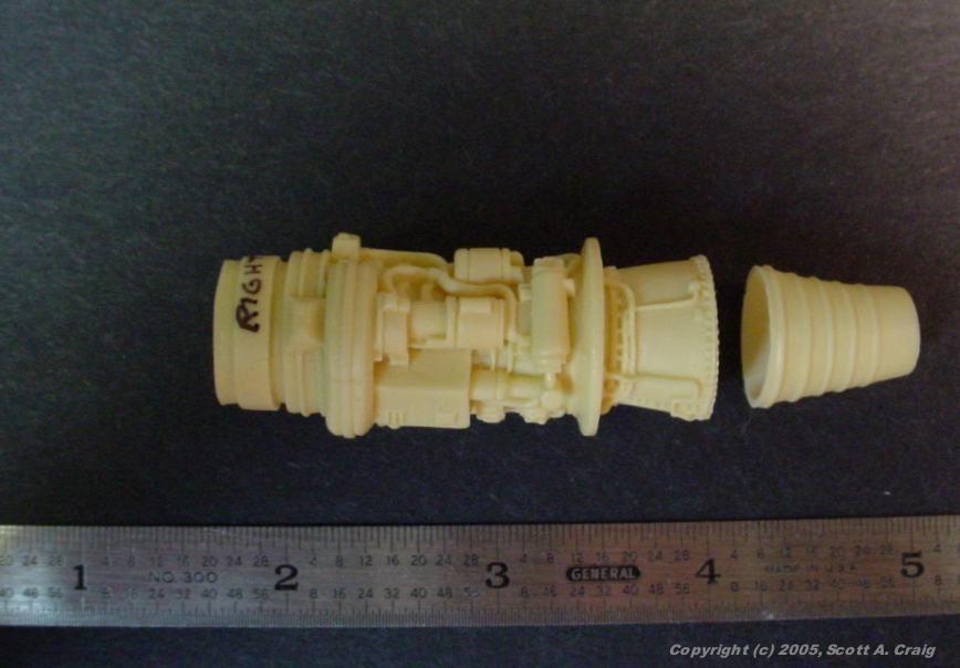
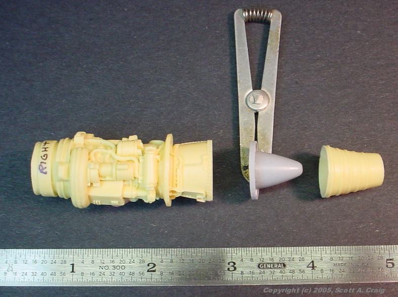
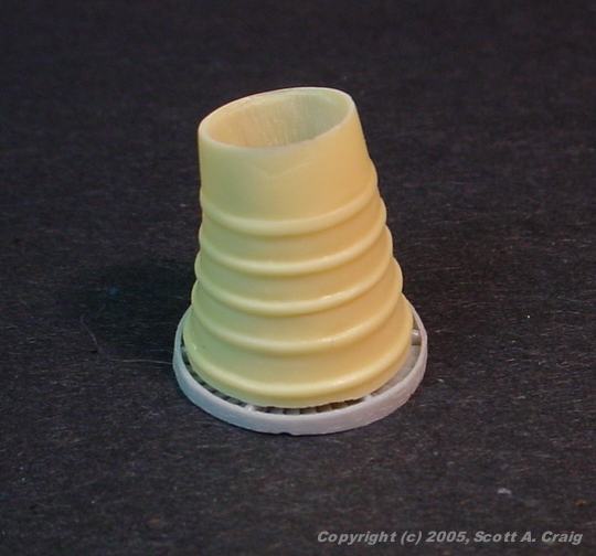
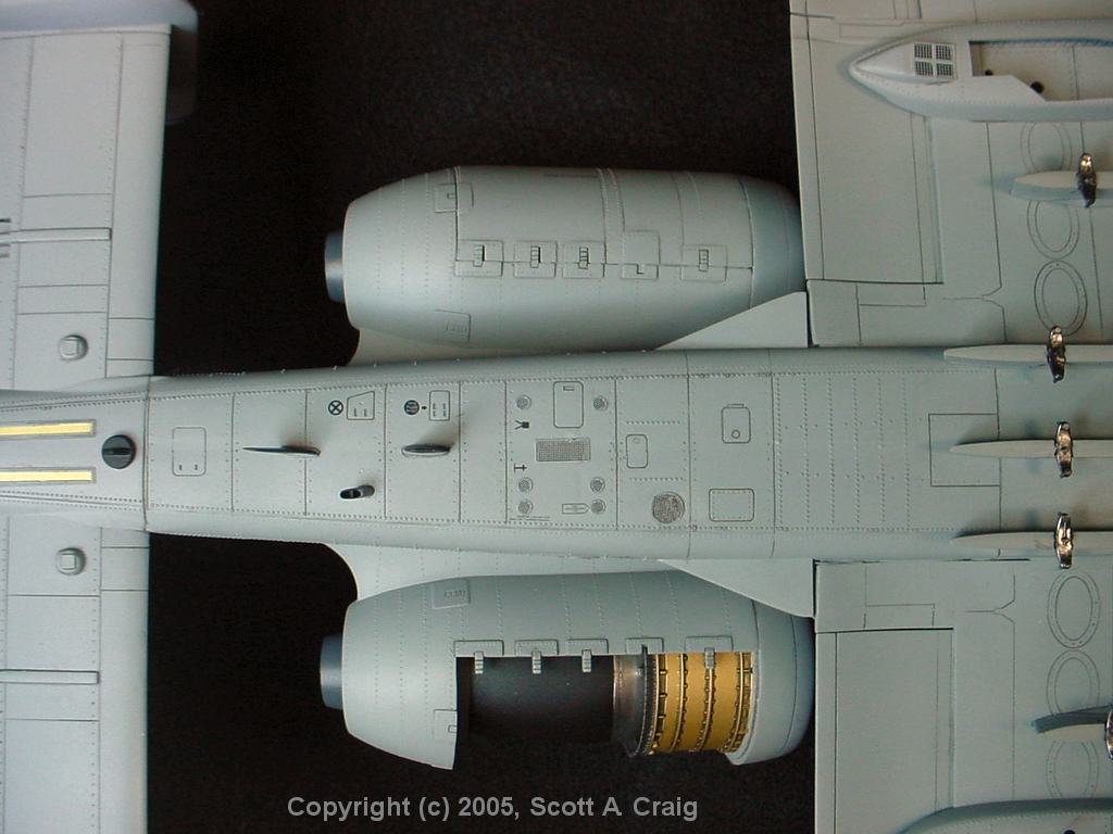
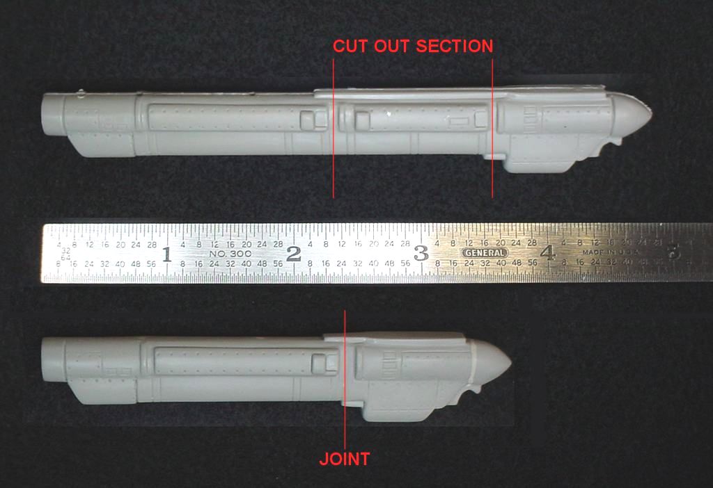
Photo 1 shows the Cutting Edge engine pod on the left. Two of them are included in the Cutting Edge Modelworks 32061 Exterior Detail Set They are solid cast resin, but if you grind and whittle away most of the resin you'll find the little nugget shown in Photo 2. The turbine face is what is needed in the Trumpeter engine to make it look right. Photo 3 shows where I CAREFULLY! sawed the Trumpeter engine into two pieces. I did a lot of grinding and sanding on the exhaust cone to make it as thin as possible. The Cutting Edge turbine face is slightly big and for the turbine slots to be visible you have to get the exhaust cone very thin so be careful! Photo 4 shows the intended reassembly (sorry about the soldering heat sink used to hold the turbine face in the photo but I couldn't get Silly Putty to hold it up). The Trumpeter engine, then the Cutting Edge turbine face, and then the Trumpeter exhaust cone. As can be seen in photo 5 the Cutting Edge turbine face is slightly larger in diameter than the Trumpeter exhaust cone, but that should not be a big problem. Some sanding and gap- filling super glue will take care of any problems there. All in all the process went better than I expected, and I'm looking forward to seeing it painted and detailed. | ||
 |
 |
 |
|
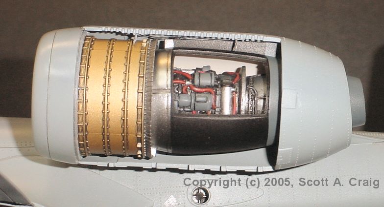
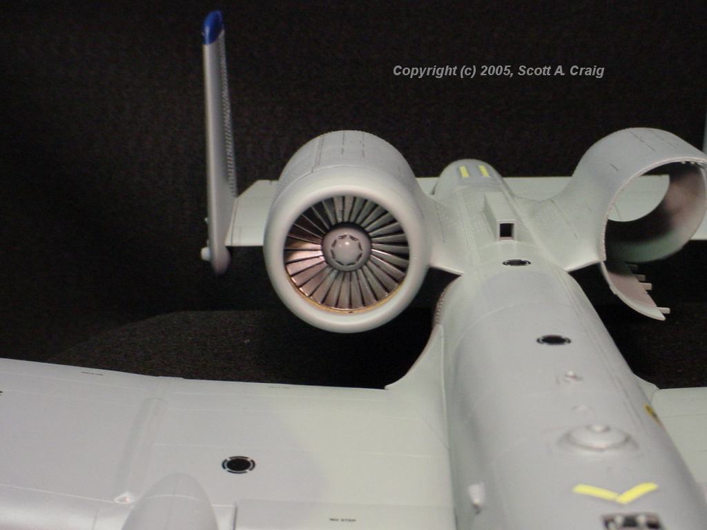
05/27/2005 Update -- Here are a couple of photos of the left engine as it will be installed. The engine is not permanently mounted in the pod in photo 7, it was just taped together for the photograph. There is some slop in the way it is mounted so it is hanging slightly lower than it really does. I pretty much went with the same wiring as John McCormick did on his A-10 at This Link. It's not exactly the same, but pretty close. John, I really appreciate your guidance, buddy. I intentionally left it pretty dirty from the wash, and may go back and add a couple of more wires and possibly make some of the details slightly glossier. All in all it turned out pretty decently. 05/31/05 Update -- Photo 8 shows the final installation of the engine. It doesn't show up well in the photograph, however I added a small lip made from 0.010" styrene strips inside all 4 edges of the maintenance panel cutout. Holes were drilled in each strip to simulate the locations for the panel fasteners. It actually looks pretty decent in real life :) The photo also makes it look like there is some overspray or speckled paint inside the housing where the inner pod mounts. It isn't really like that, it's just a trick of the light. | ||
| CONSTRUCTION UPDATE -- 05/21/05 |
 |
 |
 |
 |
 |
 |
 |
All images above are links to larger photographs. Click the image to view the larger image |
|
|
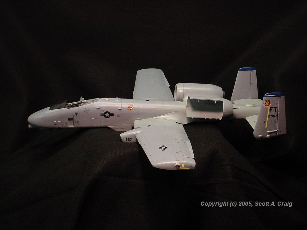
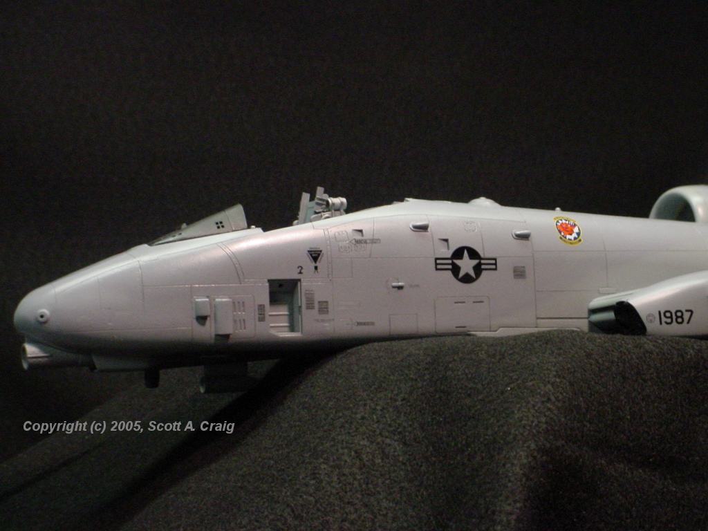
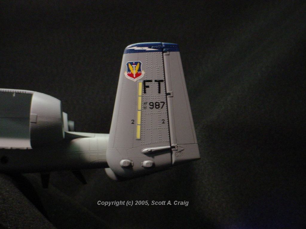
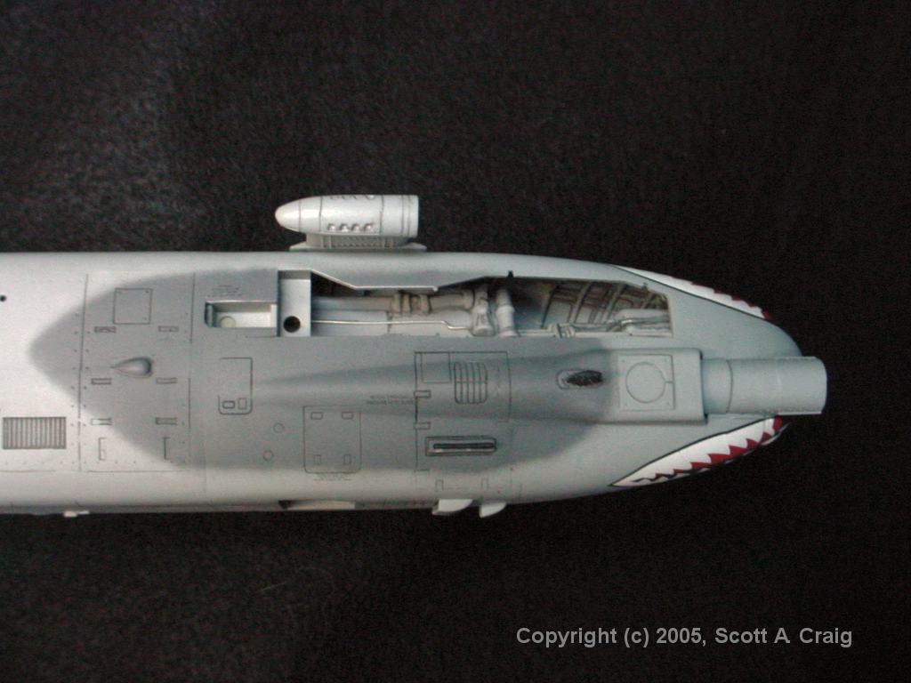
I have most of the decals on the left side, and most of the panel lines washed. The "Shark's Mouth" is conspicuously missing because I ruined the decal and am still waiting (after a week!) for some replacement decals. The left engine will be detailed and displayed with the cowling open. I don't have the engine done yet so it isn't in place. All of the yellow formation lights are not decals. As mentioned in Construction Note 14 below, the Eduard PE frames for the formation lights are larger than the TwoBobs decals so to make things look right I just painted the lights. I also noticed in photo 3 that there are a few places on the decals that need another couple of applications of MicroSol. Getting decals to settle over those raised rivets is not the easiest thing in the world. Looking at some of the photos photo I noticed that the color has a greenish cast in some areas. My bench lights are both incandescent and flourescent. I should have turned one of them off but I didn't think of it. The colors are actually light ghost gray and dark ghost gray on the upper surfaces. I also noticed after I took the photos that I forgot to put the ejection seat in the cockpit :) | ||
| CONSTRUCTION UPDATE -- 06/05/05 |
 |
 |
 |
 |
 |
 |
 |
 |
 |
| All images above are links to larger photographs. Click the image to view the larger image | ||
|
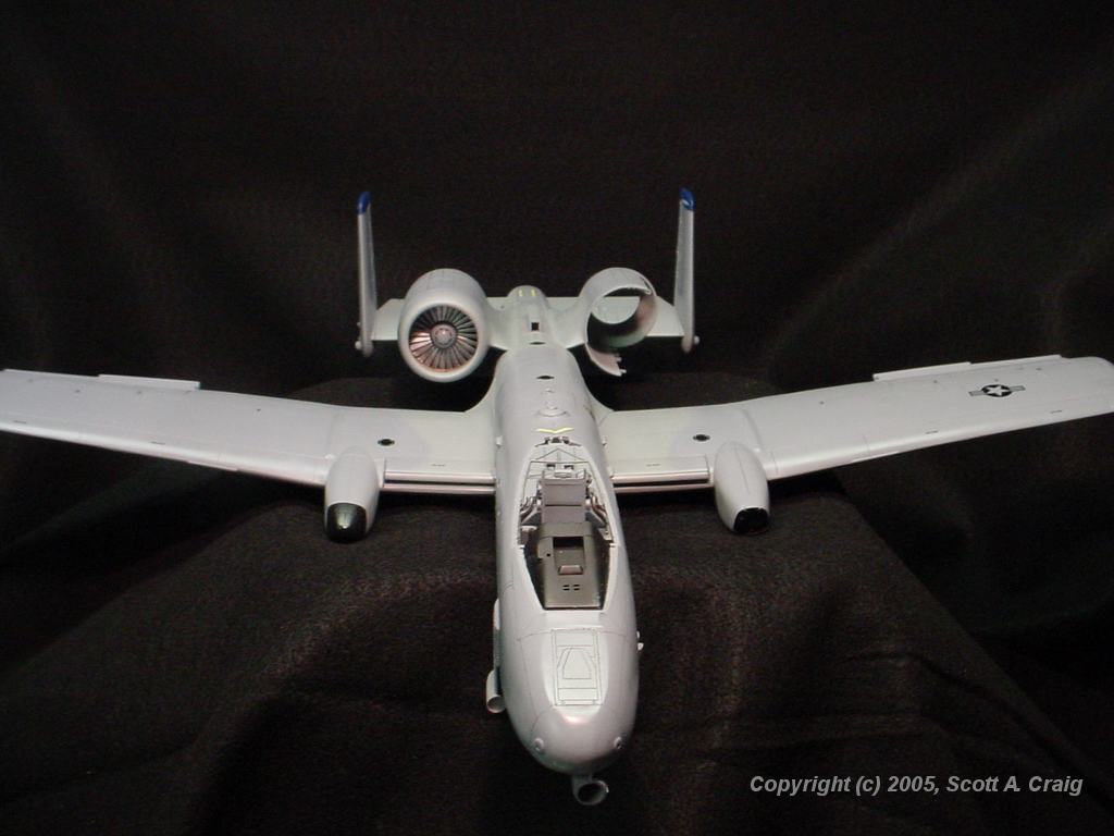
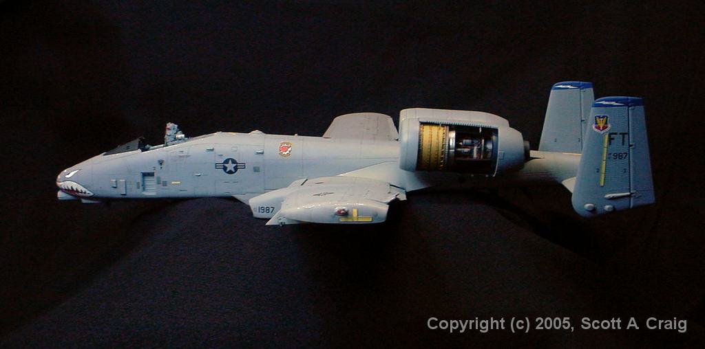
I have been working on it, it just takes time. The decals are done, the panel line wash is done and the
dull coat is done. In addition the stores pylons (all 11 of them!) are done. Still a long way to
go but at least it's looking like a Warthog now. I'm disappointed with a few minor details, but all in
all I think it looks decent.
Photo 4 is a bit dark so for the larger image I used PaintShop Pro to lighten it up some so that the engine detail shows up a bit better. That caused some of the other detail to look "Washed Out" but the photo was meant to show the engine detail anyway. If I had it to do again I'd do things like the instructions say and hold off mounting the pylons until the landing gear is done. Once I got them all mounted I realized how difficult it is to sit it down without breaking the sway braces off. | ||
| CONSTRUCTION UPDATE -- 06/19/05 |
 |
 |
 |
| All images above are links to larger photographs. Click the image to view the larger image | ||
|
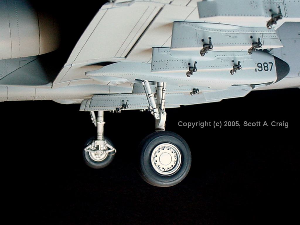
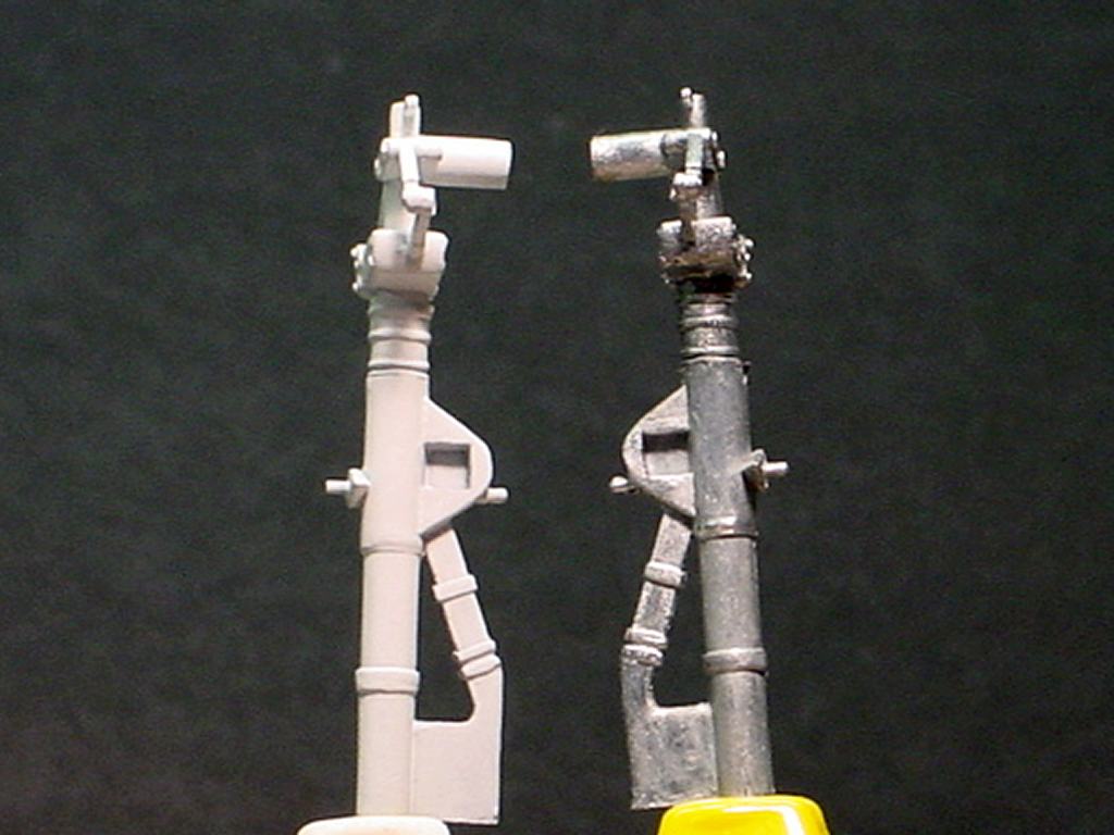
Just a couple of quick photos because I finally finished the main gear! The gear doors aren't installed
yet but the gear itself is done.
The Eduard PE set is not the easiest thing in the world to install but it really enhances the look of the landing gear. Photo 3 gives an idea of how they look without the PE set even though it was taken from a different angle. You can't tell because of the angle from which I took the photographs of the "PE Enhanced" gear but instead of having thin linkages as seen in photo 3 the linkage components now have widths that more closely resemble the real landing gear. Right out of the box the gear looks pretty decent but the PE set really adds a lot to them. The bolt heads are not part of the Eduard set, they are resin. I don't know where they came from, they were given to me by a friend. If anyone needs to know I can probably find out though. Now on to the nose gear and it will actually have three feet under it! | ||
| CONSTRUCTION UPDATE -- 07/10/05 |
 |
 |
All images above are links to larger photographs. Click the image to view the larger image | ||||||||||||||||||||||||||||||
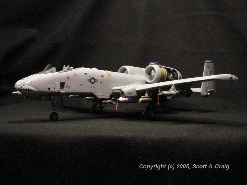
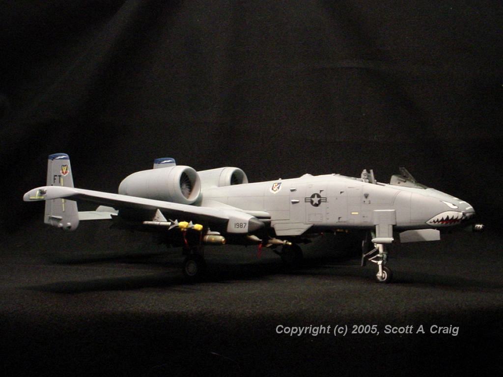
| Just a couple of quick photos. The stores are finished, and what are missing are mostly smaller items. The canopy and windscreen (which contain a good bit of resin and will take some time), a few antennae (that I couldn't install until everything on the bottom was done), the fueling receptacle door, boarding ladder, and a little bit of detail painting (some smoke stains and dust here and there). Hopefully the next couple of weeks will see this one finished. I will be glad to get it done because it has been a rough one, and there were times when I just wasn't having any fun at all. Once it's finished I'll find a nice, sunny day and take it outside for some real photos. The lighting at my workbench just doesn't lend itself to photographs very well. | ||||||||||||||||||||||||||||||||
| CONSTRUCTION UPDATE -- 07/17/05 |
| I did it! It's finished. One week short of nine months and 368 hours after I started it, it is FINALLY finished! The GAU-8 cannon will be built as a separate model but the main aircraft itself is done! I don't have any photos because for the past week we have had nothing but clouds and rain from the remnants of Hurricane Dennis, but as soon as the sun comes out again I will get some photographs. |
| CONSTRUCTION NOTES |
| Note that these
construction notes are not in any particular order. I simply added them as I noticed
them, and I was skipping around in the instructions quite a bit.
Date of last revision: July 10, 2005 | |||||||||||||||||||||||||
GENERAL ...... | |||||||||||||||||||||||||
|
John McCormick has also built the Trumpeter A-10. His article on the construction,
including some of the problems that he ran across and plenty of photographs, can be found at
This Link John has been a great source of support and advice during my construction
of this model, and I am grateful for his help.
This model is NOT for those who are inexperienced or impatient. It is not easy to build, and requires a good bit of sanding, filling, and reshaping to get it to look right. It is a rather expensive kit and by the time some resin or PE aftermarket parts are added it can become quite expensive. It is also a quite LARGE model. It is approximately 19-1/2" long with a 21-1/2" wing span so a good bit of display space will be required. Trumpeter's color references are not very good. For example, the engines are resin cast and look pretty detailed. The cowling can be left open or closed, but there are zero color references on the engine. Not a single color callout. I found a good engine reference on Club Hyper's web site that has several photographs. But, at least Trumpeter gives you a few color references. For the Cutting Edge cockpit you are completely on your own. The photos in the instructions are in black and white and there are zero color references, so plan on finding your own. Take note of Trumpeter's instructions about adding weight to the nose of this model. I don't recall exactly what their recommendation was (it seems like it worked out to about 4 ounces), but this model will be a "Tail Sitter" if you don't get some weight in the nose. The engines are resin and with all of the parts involved with them and the double rudder there is a lot of weight on the back end, and it has a pretty good moment. This, of course, will be even worse if you don't install the GAU-8 cannon. There is a hatch on the fuselage right in front of the canopy (it's actually the inflight refueling receptacle housing) that can be used to add weight in the nose if you leave it unglued temporarily. I'd recommend that you not permanently glue that hatch in place until you are certain that you won't need to add any additional weight. If you purchase the Cutting Edge exterior detail set look closely at the instructions when you get it, not specifically for the location of the resin parts but more for the model that they are using in the photographs. The model that they are using to indicate where and how the parts are installed was apparently just thrown together simply to use for the photographs. There was no attepmt to make the parts fit properly or close the gaps. In one photo they even have a piece of tape holding the fuselage together. The interesting thing is that it clearly shows some of the areas of the model itself that are going to cause problems. Gaps and areas that don't fit properly are clearly visible in the photographs. (No I won't scan the page and post it here because it is copyrighted information) While sanding it is virtually impossible to do what needs to be done without sanding off some of the raised rivets in various places. There are several ways to fix that, but one of the best I've found came from a friend in the UK (Thanks Domi!). Art supply stores have a product called "Dimensional Fabric Paint" that is used for painting designs on clothing. It's basically very thick paint but the good thing about it from our point of view is that 1) It doesn't level out when you put it in a particular place, and 2) It doesn't shrink as it dries. I used a piece of stretched sprue sanded to a fine point and put a tiny dot where I sanded the rivets off. After painting they were virtually indistinguishable from the factory rivets. | |||||||||||||||||||||||||
COCKPIT ...... | |||||||||||||||||||||||||
|
Trumpeter's cockpit is pretty bland so you may want to add an aftermarket cockpit or some
PE to give it some detail. The ACES II ejection seat is pretty good, but the side
consoles have very little relief or detail, and the instrument panel is a pretty weak
looking decal.
Cutting Edge has a good cockpit (see comment #2 below) and many of the mail order companies
list a Black Box cockpit, but I cannot find a listing of it on the
Black Box web site. Eduard also shows
an A-10
Interior Detail Set that looks like it has a lot of detail.
If you go with the Cutting Edge cockpit, look it over CLOSELY when you get it. My instrument panel was VERY poorly cast (a couple of the instruments were nearly closed with overcast, and some of the switches and controls had so much overcast it was difficult to tell what they were) and the top left ejection seat launch rail on the tub was broken off. The instrument panel has two options:
I fixed the broken ejection seat launch rail with a small piece of "U" shaped styrene. Visibly you can't see anything wrong now, but it's a shame that I had to fix the problems because the rest of the casting and detail is fabulous. One thing about this cockpit that I find very interesting is the ACES II ejection seat. Cutting Edge did such a well-detailed job of designing and casting it that it doesn't even have to be glued into the cockpit. The launch rails are molded into the tub, and the seat itself actually has the rollers molded in that guide the seat up the rails when it is launched. The rollers slide into the channels on the launch rails, just like the full-sized seat would do, so I just slid mine down the rails and left it that way. The instructions say to glue it in, but I saw no reason to do so since it fits just fine without any glue. The Cutting Edge cockpit has two parts that they refer to as "Ring Brackets" that fit just behind and to the left of the ejection seat. While their description is technically correct, the fact is that these "Ring Brackets" are there to hold a thermos bottle. The thermos is sometimes taken out, a tube installed, and the area used to store the pilot's helmet bag. This can be seen in This Photo. The caption for this photo reads: Shot of pilots helmet bag holder note: this may be a 175th wing mod only it was where the thermos bottle was originally when delivered from Fairchild I don't think this mod was specific to the 175th wing only, as indicated in the caption, since I have seen other photos showing something similar. The thumbnail for the photo, along with the caption, is shown on This Page To add this tube you'll need to find a piece of tubing approximately 0.157" in diameter (outside diameter) x 0.250" long. Regardles of whether you use the kit cockpit or the Cutting Edge cockpit, the base for the HUD is incomplete. It has a round area molded into the HUD base between the HUD braces. This is the projection lens and have a dark green tint to it. It should also look more like a lens. I used a landing light from an old Spitfire model and cut and trimmed it to fit. Even painting the inside of the circular area dark green and then filling it with Future would look better than nothing. Thanks to Snake, Dennis, and Joe for helping me with this one and clarifying the color and what it actually is. | |||||||||||||||||||||||||
FUSELAGE, WINGS, EMPENNAGE ...... | |||||||||||||||||||||||||
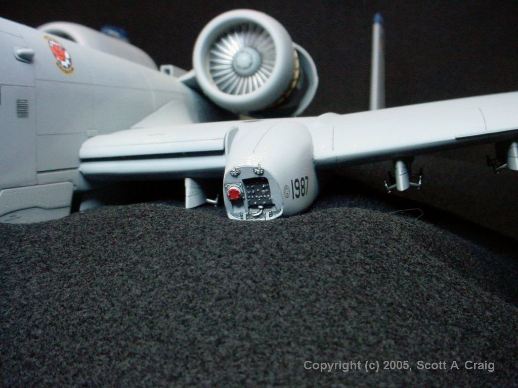
|
The worst thing I've found about this model (so far!) are the wings. The fit of the
parts is just plain bad. The flight control surfaces are difficult to get to fit
decently (I gave up trying to get them "Right" and just settled for "Decent"). The
bottoms of the wingtips are turned down, and where the top and bottom halves join there
are huge gaps that are difficult to fill and clean up. They can be cleaned up though,
it just takes some time. Additionally there are two panel lines on the leading edge
of the bottom that don't even come close to lining up with the corresponding lines on the
top. The only way to fix that is to fill and rescribe them, but be sure to fix
the lines on the bottom half. They are the ones that are angled wrong.
The wings themselves do not fit the fuselage well. I probably should have done more "Dry Fitting" but I don't really think it would have helped. I wound up putting about 0.035" of shim between the fuselage and the bottom of the wing to close the gap. I prefered to use a shim there instead of putty because the wings will have a pretty good load on them and I am afraid that putty would eventually crack or pop loose from the strss. The refueling port (on the front of the left main gear sponson) is wrong. The kit has it molded vertically when in reality it slopes downwards. You can see how it is slanted in these pictures on the ARC web site: Photo 1 Photo 2 Photo 3 The Cutting Edge 32061 exterior detail kit contains a resin replacement for this assembly that corrects the problem. Alternatively you can try to modify it yourself. Trumpeter's instructions do not show this very well, but if the slats on the leading edges of the wings (parts K-25 and K-26) are installed in the raised position the trailing edges should not touch the top of the wing. They should pretty much follow the contours of the fences beside the ends of them. Mine have approximately 0.040" of clearance between the slat and the top of the wing. Thanks to John McCormick for pointing that out. I've looked at several pictures of parked A-10s and it appears that there is no "Standard" way for the slats when the aircraft is parked. I've seen pictures of them with the slats both raised and retracted so either method seems acceptable. If any of the A-10 gurus read this I'd appreciate it if you'd drop me an Email and let me know for sure. Update - 07-15/07 - I received an email from an A-10 Crew Chief who provided the following information: I don't know if anyone has answered this yet but I will give you what I know. The slats are pinned in the nose on recovery of the aircraft. Once you put the pin in the slats are supposed to go into the maintenance position (or the raised position). However because of the aging actuators (the aircraft uses two per slat) and the fact that most actuators are reworked and reused many times they don't always stay in the raised position and you see the "drooping slats" that appears in most pictures. The pin is supposed to keep the hydraulic pressure in the actuators and keep the slats up for maintenance and inspection between the slat and the wing. If you have anymore questions Ill be happy to try and answer them. The second thing I saw was the ring brackets are no longer used in the aircraft and have been removed and replaced with a box like object called the DTC that the takes a special made digital recording tape. Also many of the gun bay scoops on the left forward side of the nose have either been removed or are being removed during the A-10 upgrades. Thanks, Chris, for the help and input. It's guys like you who help to keep the rest of us on track and we appreciate it. | |||||||||||||||||||||||||
ARMAMENT AND STORES ...... | |||||||||||||||||||||||||
|
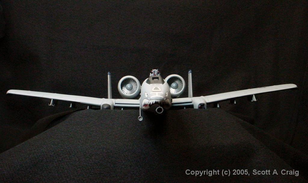
The muzzle brake on Trumpeter's cannon is just plain wrong. For one thing, the ports in
the sides are filled and should be open. This can be fixed by drilling them out, but then
you will see that the cannon barrels do not go all the way to the end of the muzzle assembly.
They stop at the rear of the muzzle assembly, and if you drill it out and push it farther down on
the barrels, the muzzle brake will go back inside the fuselage.
The muzzle brake should be similar to what is shown In This Photograph. Notice that there is a line of three holes for each barrel and that if you look through the holes you can see the individual barrels. There are a couple of ways to resolve this:
The kit comes with an AN/ALQ-119 ECM pod. Presumably for the birds that the kit is designed around that is OK. If you are building a Desert Storm or Iraqi Freedom bird it may not be suitable. In some cases the did carry the AN/ALQ-119 pod but in many cases they carried an AN/ALQ-131 pod. Flightpath Products makes a good resin replacement for the AN/ALQ-131 pod (click this link for a picture of it) that is available through Greatmodels however it is a "Special Order" item and may take a good while to get. The model that I'm building is of an Iraqi Freedom plane and it carried an AN/ALQ-184 ECM pod. Nobody that I have been able to find makes a 1/32 scale ALQ-184 pod. I am not alone in this and after doing some searching on the internet I found that a couple of others who have run into this problem modified the ALQ-119 pod that came with the kit, and after looking at some pictures of them I could see how it could be done. It appears that the ALQ-184 is similar to a shortened ALQ-119. I sent an email to one of my "Experts" and he verified that the AN/ALQ-184 is similar in appearance to a shortened version of the AN/ALQ-119 pod (thanks, Dennis!).
AN/ALQ-184 (Left Side) ---- AN/ALQ-184 (Right Side) As you can see by looking at the larger image above my conversion is not finished by a long shot. I still have a good bit of sanding to do and will have to rescribe some of the panel lines that were destroyed by the sanding. You can also see where I filled the groove around the nose. When I assembled the halves the groove didn't even come close to matching from one side to the other. The only thing to do was to fill it and rescribe it. The real one doesn't have a big huge groove there anyway, and I still need to fill the one at the rear. Here is the list of stores that I used. It isn't completely historically accurate in that the stores were not necessarily carried by this particular aircraft during Operation Iraqi Freedom, but they could have been carried. The problem is that some of the items I need are not readily available as aftermarket parts nor were they included in the kit. I'll probably run across what I need sooner or later and shift things around so they aren't permanently mounted to the pylons. Thanks to Dice, 72Cuda, Trigger74, and Sharkskin for their help and advice.
And, of course, there is always the massive GAU-8 cannon! The AIM-9 Sidewinder missiles are just lousy. First off, they are not AIM-9L's as shown in the instructions they appear to be AIM-9B's. Next, the missile consists of two parts; A main section which contains all four front fins and two of the rear fins, and another part for the two remaining rear fins. My parts contained a lot of bad casting between the front fins that was very difficult to smooth out (in fact I finally had to putty some deep scratches and then sand it down), and they contained some ejector pin marks on the rear fins that had to be filled with putty and then sanded. The worst part, though, is the way the rear fins fit onto the main missile body. The part that makes up the two rear fins slides into a groove on the main body of the missile. There are also some significant gaps at the front and sides of the fins in places. The desing of the fins leaves the back end of the missile looking like a cross with no exhaust. I plugged the gap with 2-part epoxy and then carefully drilled a 3/32" hole into the rear of the missile. I started with a #80 bit and incrementally worked my way up to 3/32. They look a lot better than they did in the beginning, but my recommendation would be to throw them back in the box and get a couple of resin replacements such as those offered by Cutting Edge or some other vendors. They would look a lot better and probably be easier to build than the ones that came in the kit. I've been told that the Dual Rail Adapter (DRA) that accomodates the two AIM-9 missiles is not exactly to scale. I didn't verify that myself, so if you are a stickler for accuracy you may want to take some measurements and see what you think about it. Some of the CBU-52 cluster bombs are pretty bad. When you put the two halves together you'll see that the engraved panel lines don't even come close to matching up. For most of us this means filling and rescribing the lines. I found one that was pretty close (it still needed some rescribing but the panel line got wasted when I sanded down the joint between the halves anyway!) and then chose to use a MK-20 Rockeye on the opposite pylon. The MK-82 bombs do not have a lot of detail and I'm not sure about the fuse that Trumpeter used. It may be a radar fuse but I could not find any photographs of a MK-82 that had a fuse that looked like that. I chose to use two that came with my F-105G since they had more detail and just generally looked better. | |||||||||||||||||||||||||
DECALS ...... | |||||||||||||||||||||||||
|
Time for a little humor at Trumpeter's expense ... Look very closely at the decals on the main
decal sheet for the manual canopy release. They are on the sheet with the "Stars And Bars"
and are decals number 19 and 20. If you look real close you'll notice that they misspelled
"Canopy". It is spelled "caMopy" (with an "M"). I assume that the line beneath that
reads "Releas Manele" means "Manual Release" in some other language. If not, they misspelled
that as well. And finally (at least so far!) look at the decals for the AGM-65 Maverick that
reads "No Lift". Look closely! They actually read "No Life".
I am a big fan of TwoBobs decals. Bob Sanchez does a great job on his decals, both in the graphic design and the research that goes into them. His decals are always very thin, very opaque, and very complete right down to the smallest marking. This sheet, however, does have a few problems to deal with.
| |||||||||||||||||||||||||
MISCELLANEOUS AREAS ...... | |||||||||||||||||||||||||
|
I'm a bit confused about the engine exhausts. Not only are they wrong, they don't exist!
The two engines are resin and the back end is completely closed up. None of the
reviews of this model that I read mentioned that, and I can't understand why in the world
Trumpeter would cast the engines that way. They are usually very good about detail, and
this is a distinctive error.
Here is a link to what the engine exhaust should look like (the photo shows the engine inside the engine cover, so the actual exhaust is the inner shroud). As can be seen there is a diffuser and cone in the center that is not in the kit. As mentioned above in the construction notes I am using the turbine faces from the Cutting Edge exterior detail kit for the back of the engine. This kit contains complete resin exhaust cones, however if you use them you will probably not be able to display the engine open, and trying to paint the exhaust vanes will be very difficult. Be sure and leave some room in your time budget for fixing this gaping problem! If you want to go the lazy route you could always come up with some engine covers! Note that I have been told by another person who has the N/AW two-seat version that his engines are hollow, so maybe mine were just weird for some reason. Unlike their F-105, Trumpeter thankfully provides cast metal landing gear for this one. Plain old plastic landing gear would never hold up the weight of this monster. The set included with my kit was in pretty decent shape, but it still needed some cleanup to remove the casting flash. Here Is A Link to the method that I use for metal parts. It took me about an hour to do the cleanup and priming on each gear strut, and most of that time was spent filing the flash off. If you use the Eduard PE set plan on spending a good bit of time getting it to fit properly. The results are well worth the effort, but the effort involved is significant. | |||||||||||||||||||||||||
| CONSTRUCTION TIME |
|
For anyone who might be interested, here is how my time breaks down so far. Keep in mind that I don't
punch a time clock or anything like that. After I work on it a while I write down approximately how
much time I spent on it and what I did. It's relatively close, but not exact by any means.
|

._Large_tail_Winder_used_on_USAF,_USN,_and_foreign++Fri_07_08_20059_0_46.dat+14.99+)